The entire project was divided into several stages and stretched over an indeterminate number of months. There was no reason to rush, so each stage was carried out as meticulously and thoroughly as possible. This part of the story focuses on the very first stage — the preparatory one.
This preparatory stage could very well have been the last, as its results alone would determine whether it was worth spending even a single cent or minute of time on the project moving forward or whether it would be better to abandon the idea and redirect resources to something else.
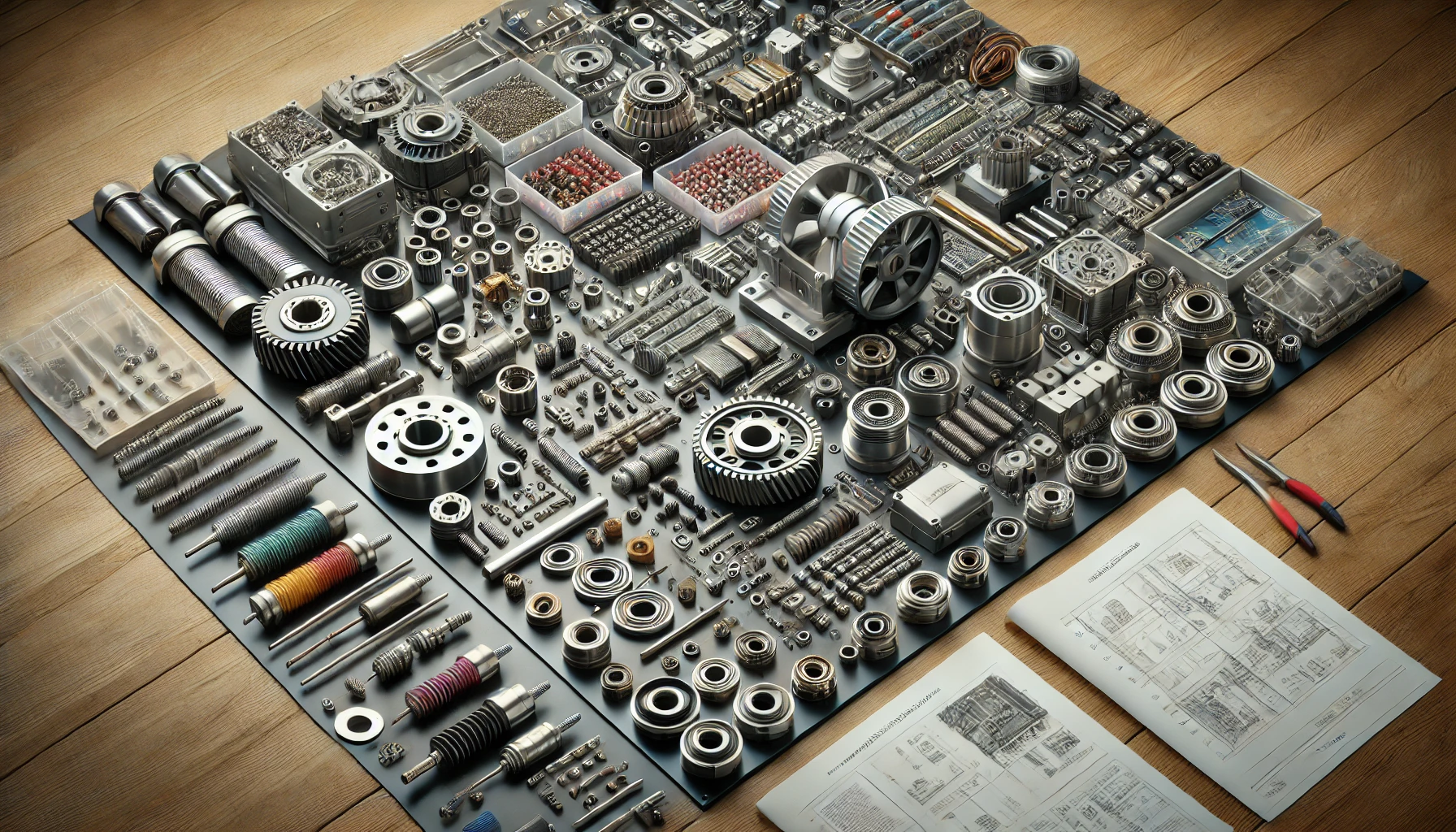
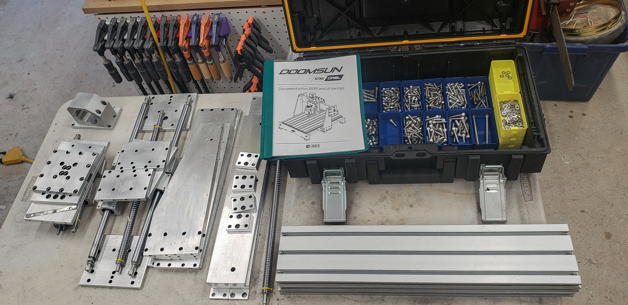
According to the overall plan, it was necessary to turn the existing pile of aluminum into something resembling a kit, from which a new machine could later be assembled. In addition, it was essential to create accompanying technical documentation: to determine what kind and how many fasteners were needed, to have a complete list of all parts with their dimensions (in case new ones needed to be manufactured), and to outline the assembly order, among other things.
The task was to completely disassemble everything, simultaneously identifying what required replacement, what could be repaired, and what could be reused as is. This also included attempting to correct as much as possible the consequences of poorly executed work, metaphorically referred to as the handiwork of “clumsy-handed Chinese.” In essence, this meant performing a thorough exorcism so that, literally, not even a trace of their influence would remain near the machine.
Next, during this stage, it was necessary to select a control system for the machine. This included deciding which controller would manage everything, which motor drivers to use, what type of power supply was needed, and so on. These decisions needed to be addressed at a theoretical level during this stage in order to understand the direction of development.
There is a significant difference between flashing GRBL firmware onto an Arduino and using an onboard microcomputer with LinuxCNC or something similar. The choice of control system would determine the set of components required, as well as the scale of the effort, time, and financial investment needed.
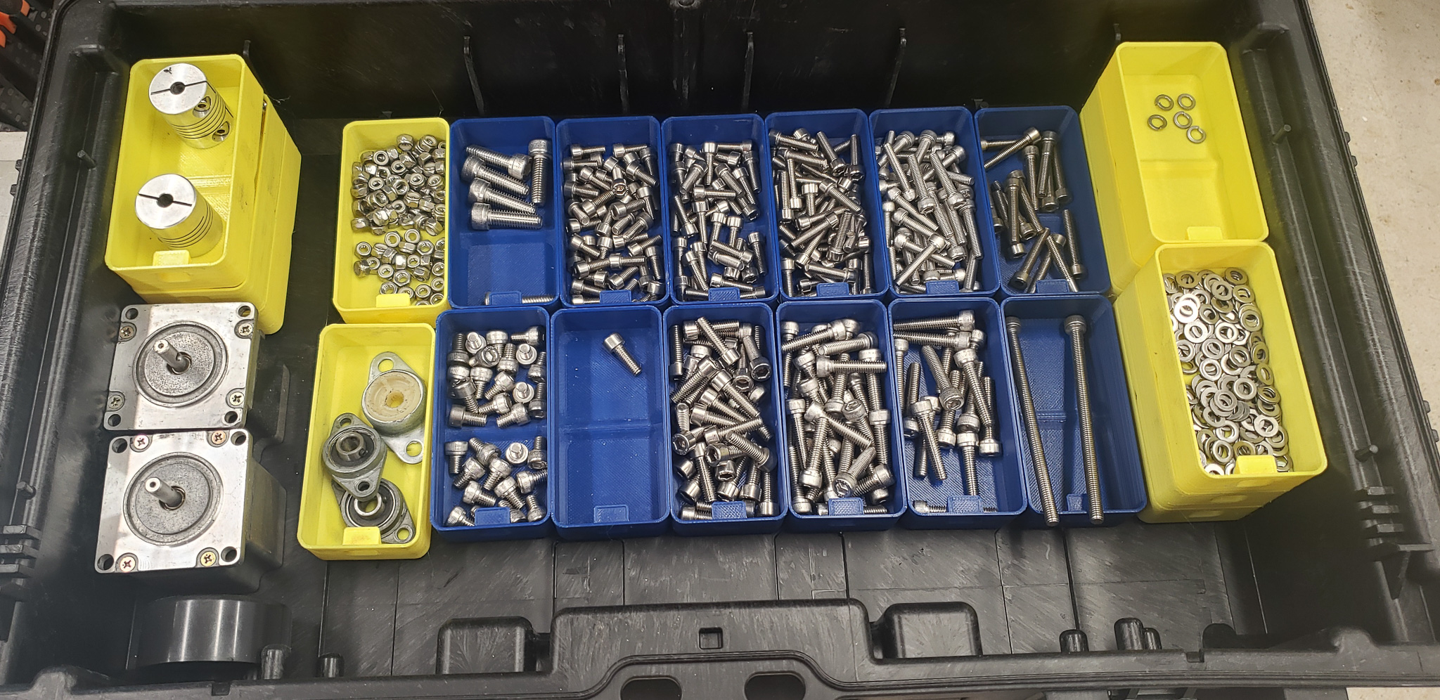
Based on the results of all the operations described above, a detailed list of necessary components, spare parts, and fasteners would need to be compiled for procurement or further consideration.
The final outcome of this stage would involve making a decision about the project’s future. If it turned out that the set of surviving parts accounted for approximately 60-70% of the project’s requirements, it would make sense to proceed. If less, the project would head to the morgue as a source of spare parts and materials for other endeavors.
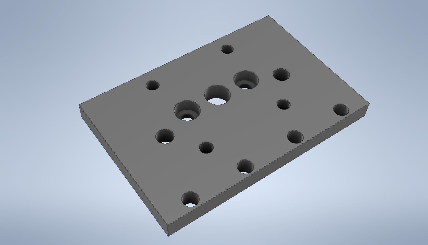
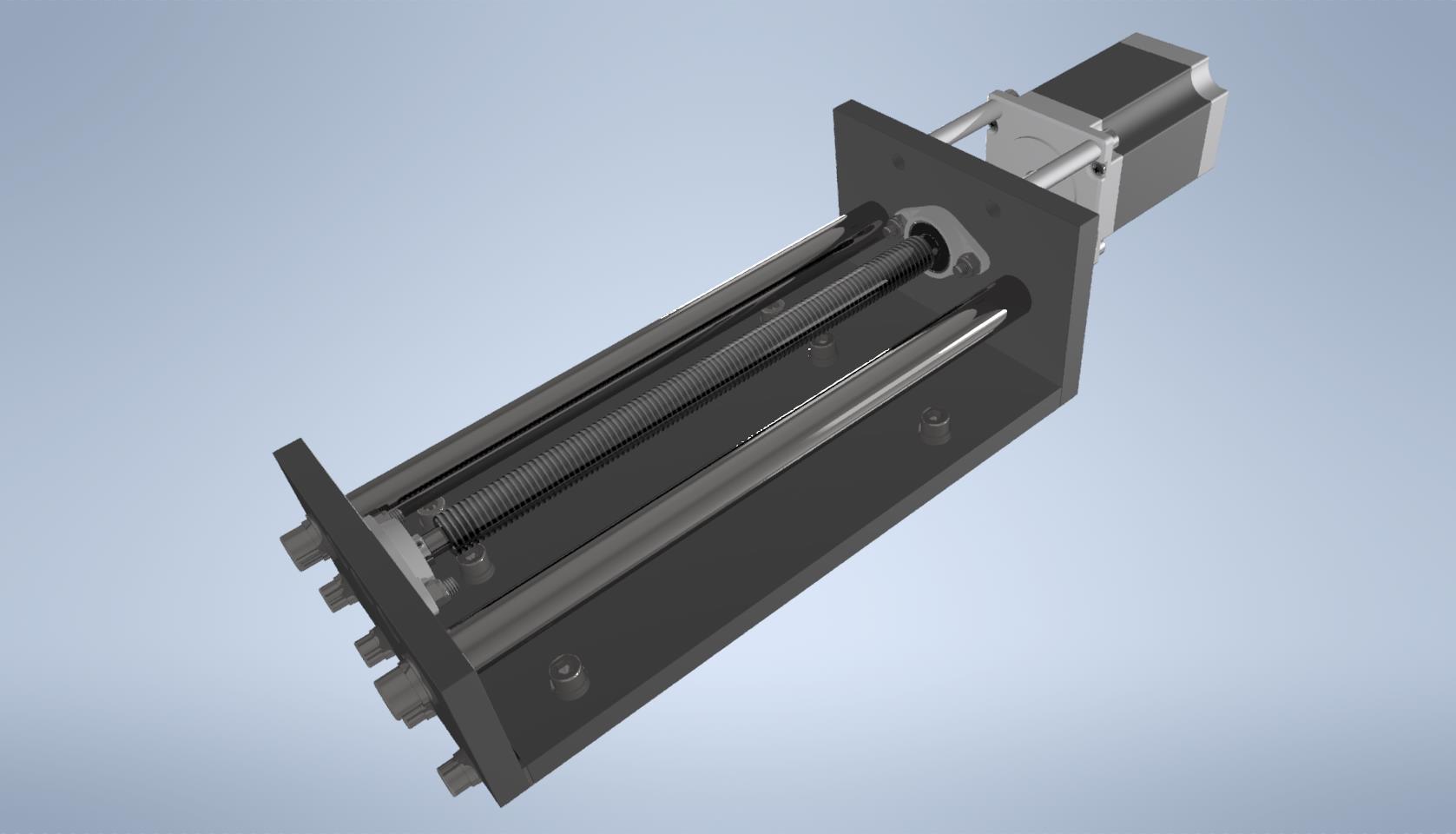
The entire process unfolded as follows… A component assembly “on the surface,” meaning one that was easiest to access, was chosen. This assembly was completely disassembled into its individual parts. For example, the parts of the XY axis carriage:
Детали очищаются от старой краски и исправляются, если это возможно. Все отверстия зенкуются, со всех кромок снимаются фаски, поверхности шлифуются и т.п. Абсолютно все резьбы в деталях прочищаются проходом нового метчика.
Each part was cleaned of old paint and repaired if possible. All holes were countersunk, all edges were beveled, surfaces were sanded, and so on. Every single threaded hole in the parts was cleaned with a new tap.
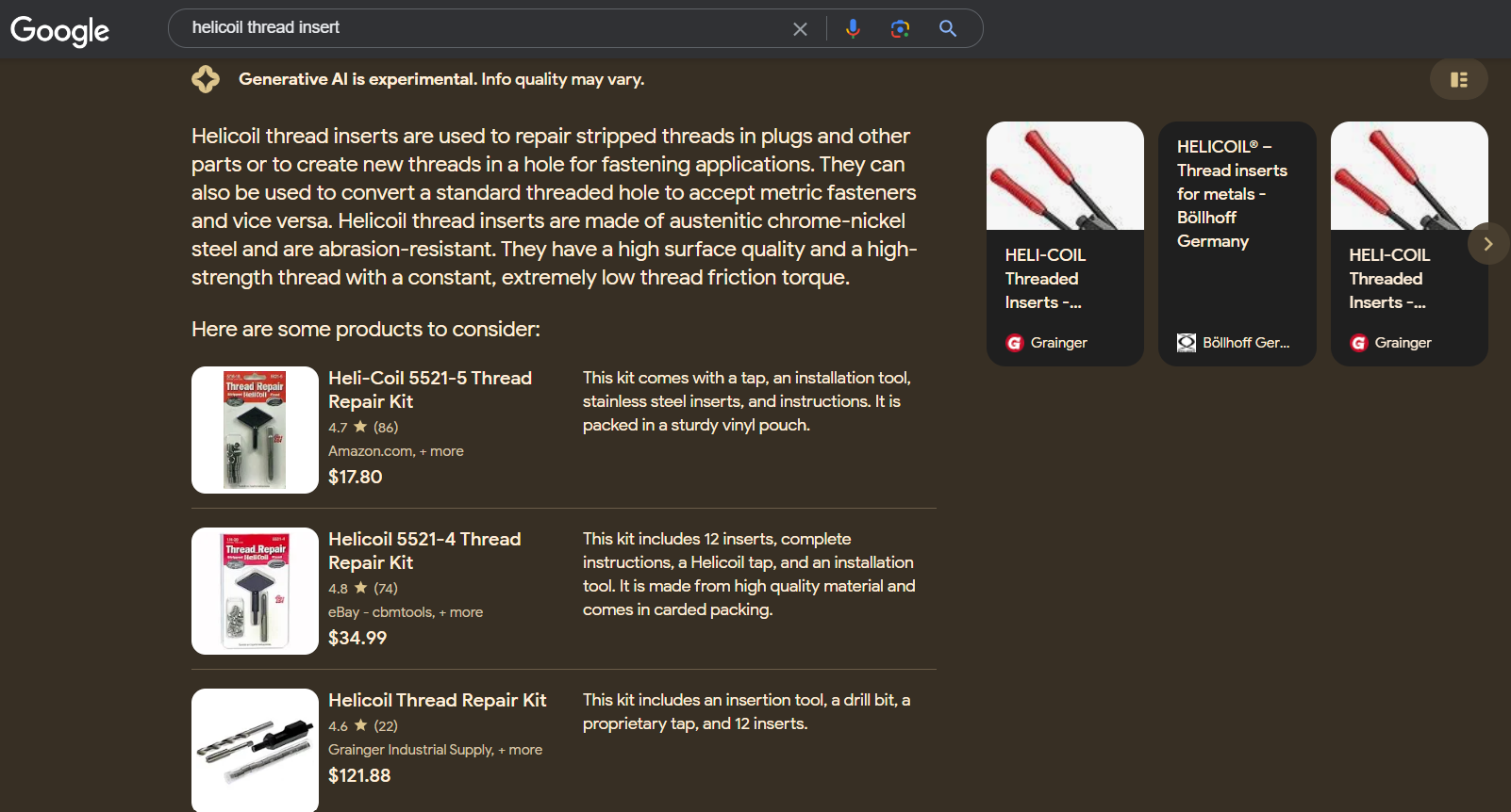
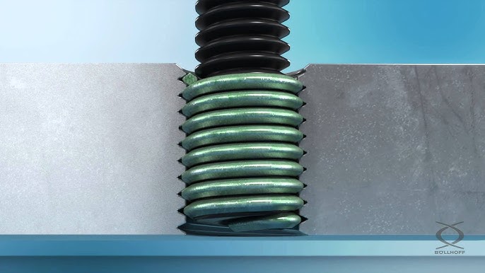
In some particularly problematic cases, threaded holes had to be drilled out to a larger diameter and restored using coil inserts or helicoil thread inserts (see Google and YouTube for details):
This method made it possible to fix most of the misaligned holes and poorly cut threads.
Unfortunately, not much could be done about holes that were drilled off-mark. However, this was not a major issue since the clumsy monkey that created these parts apparently drilled the mating parts “on the spot.” Consequently, the mating part had a similarly misaligned hole, so everything — more or less — fit together in the end. As a result, nearly all parts were, grudgingly, deemed more or less acceptable after repair and restoration — though a heavy sense of disappointment lingered.
At the same time, a 3D model was created for each part, with dimensions taken directly from the physical component.
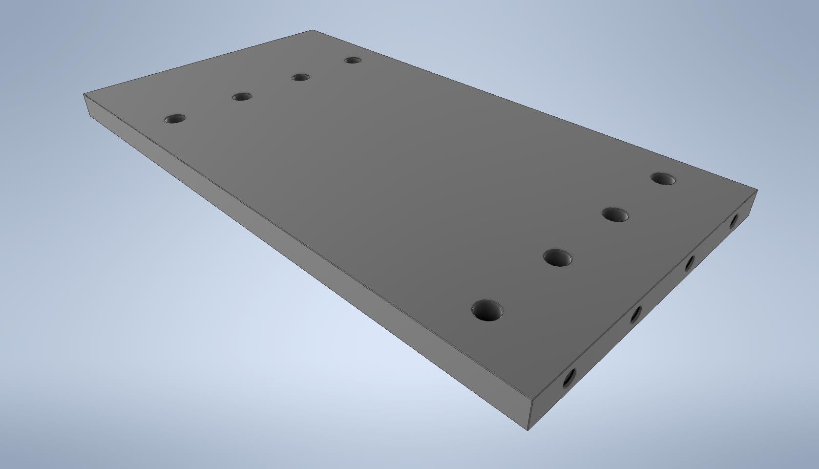
The 3D models of all parts were then assembled into a single digital structure with all necessary fasteners. Bolts, nuts, washers — everything was modeled exactly as it should be in reality. Fortunately, modern CAD software eliminates the need to manually draw all the fasteners — they can simply be taken from a standard library and automatically added to the project:
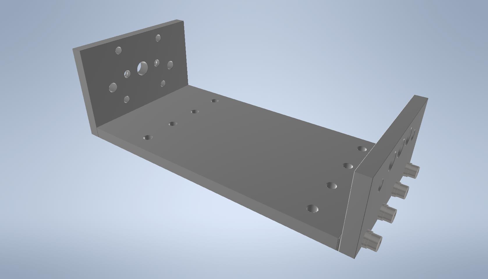
Later, these subassemblies were combined into the final structure using the same principle:
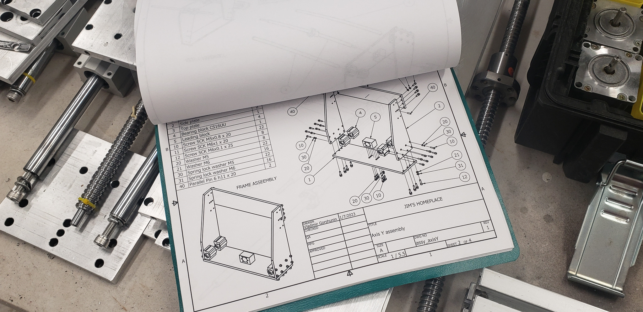
With just a single click, I can now generate a complete list of every single component that makes up the machine, including the number and type of bolts required.
Similarly, assembly diagrams are almost automatically generated, showing which part connects to which and which screw goes where:
Piece by piece, a sort of kit for assembling the machine came together. It included a detailed description of all components and fasteners:
The next step was to integrate electronics into the project. At this stage, the actual control block didn’t need to exist in its physical form yet. However, it was crucial to have a clear understanding of what it would look like and what components would be required.
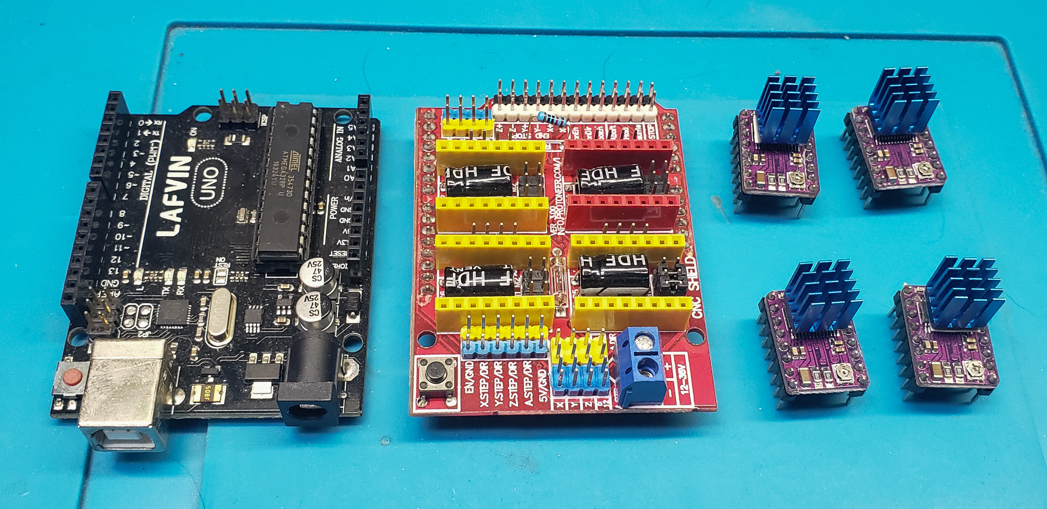
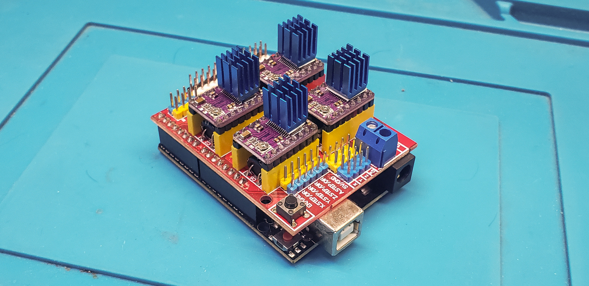
Yes, of course, I already had a ready-made setup lying around, based on Arduino Uno board:
Essentially, this was an almost complete controller, only lacking a power supply and motor wires. But… “Man, admit it, you didn’t come here just to hunt,” as the bear would say (loosely quoting a famous phrase).
By the way, this wasn’t the first robot I’d built. I had plenty of devices in my projects where this setup could theoretically be used. Yet, it kept sitting in storage… probably for about ten years now. Every time I’d take it out, dust it off, and after some deliberation and exploring alternatives, put it back. Such a useful and necessary setup… an incomplete relic of the past.
At one point, I had the opportunity to work with a CNC machine controlled by LinuxCNC. A massive beast the size of a shed. And “it had a neon inside!” Meaning, just an ordinary “Raspberry Pi.” Not the standard Raspberry Pi but the Compute Module version. Still, fundamentally, it was just a regular Raspberry Pi.
Sometimes, the inertia of thought plays cruel jokes on us. Following this inertia, all my ideas stubbornly revolved around the idea of running LinuxCNC on a Raspberry Pi. After all, I had plenty of those gathering dust in my stash as well.
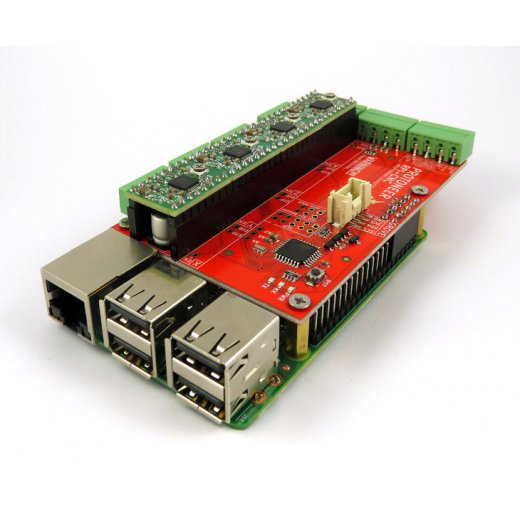
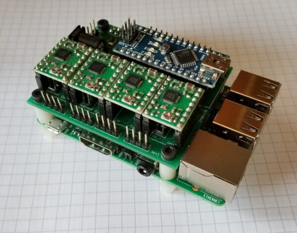
The problem, however, was that ready-made CNC “hats” for Raspberry Pi generally relied on low-power stepper motor drivers that were often mounted directly on the hat itself. For example:
Even worse, in many cases, the Raspberry Pi served merely as a “computer,” while an Arduino or similar device acted as the actual “controller” managing the motors:
But I’d already had enough experience with low-power drivers. They’re fine for something like a 3D printer, but not for a CNC router. Such drivers typically can’t deliver enough power to the motors, causing missed steps when material resistance increases — and, well, you know how that ends.
For this very reason, my mid-sized CNC machine for woodworking often struggled with anything harder than MDF panels or basic planks. If it was oak, it was game over! You’d have to cut at a painfully slow pace with an extremely shallow depth per pass. The motors and spindle were fine — even the shortest Nema23 motors are beasts in terms of torque. But what’s the point if the driver can only supply half the allowable current at best?
Consequently, the idea of using high-power external motor drivers was embedded into this project from the very beginning.
Finding a Raspberry Pi “hat” compatible with external drivers turned out to be quite the challenge! Strange as it may sound, that was the situation at the time. I scoured the entire Google search engine and came up nearly empty-handed. Occasionally, I’d come across hats with additional outputs for external drivers, but they were either poorly designed, overly complicated, or incomplete.
Sure, there was nothing stopping me from taking a standard hat designed for onboard drivers, rigging up “dummy plugs” with outputs for external drivers, and calling it a day. I could even design my own custom hat. That wouldn’t have been too difficult either. But all of these felt like makeshift solutions, cobbled together with duct tape and wire. I wanted something… I wasn’t sure exactly what… but something that worked seamlessly, out of the box. I was tired of piecing things together with spit and string. There was already enough of that in the mechanical part of the project.
So, I kept mulling it over, swinging back and forth between the extremes of “GRBL on an Arduino” and “LinuxCNC on a Raspberry Pi,” as if nothing else existed in the world.
Yes, I was aware of ready-made specialized “controller boxes” for CNC routers.
However, these still required an external computer for control, and their prices… well, let’s just say they weren’t appealing. And internally, they weren’t much different from “an Arduino with GRBL” — just with more hassle for a DIY enthusiast. I’d dealt with such solutions in the context of industrial equipment and glanced at them as an option, but not too closely.
These mental gymnastics came to an end one evening when I needed to tweak the firmware on one of the light switches in my house. We had a disagreement over what should count as “movement in the room” — or rather, the disagreement was between the switch and my cat… but that’s beside the point.
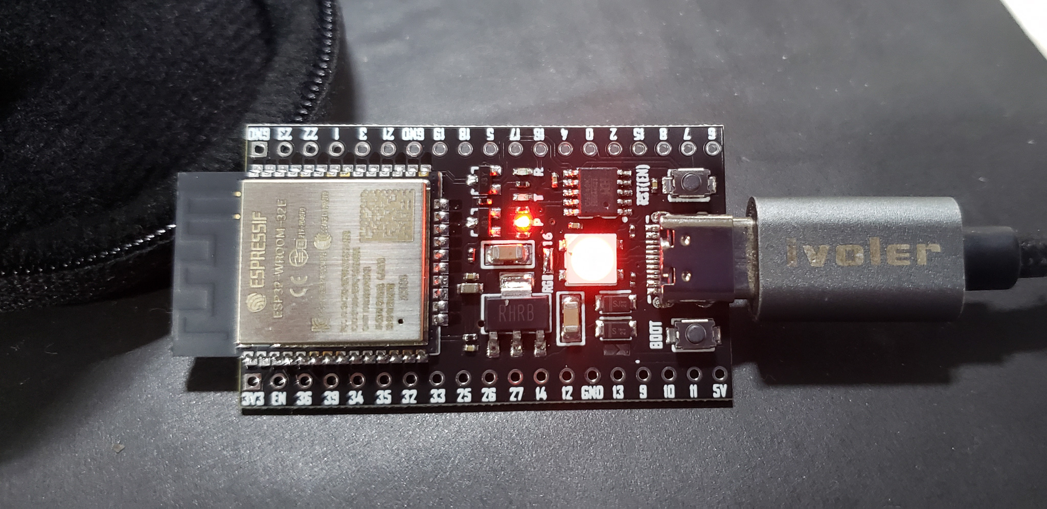
I had already transitioned all the controllers in my smart home to use the ESP32 microcontroller. And it was at this moment that the idea finally struck me: why not explore using the ESP32 as a controller for the CNC machine? In hindsight, it seemed like an obvious idea that should have occurred to me from the start. It’s a shame how inertia and professional bias can blind you. Don’t be a slave to it!
Unsurprisingly, the very first Google searches led me to a GRBL port for the ESP32, and from there to a specialized branch called FluidNC, which solved all my problems.
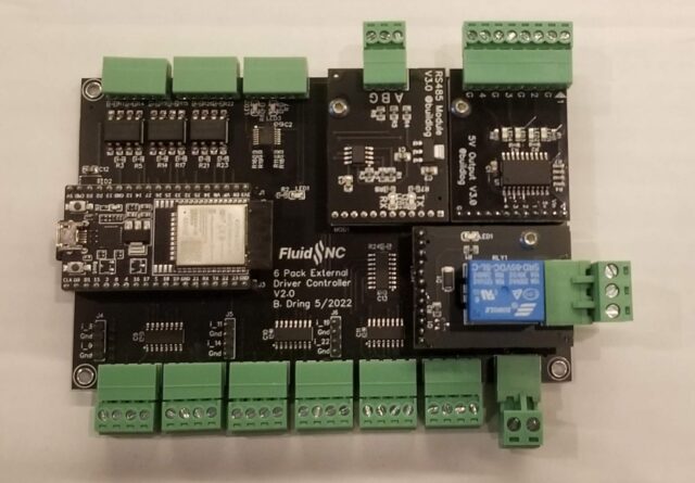
First, there was already a ready-made board for FluidNC designed for use with external motor drivers (6 Pack 2.0 External):
No need to search or invent new solutions. The author even sold these boards as fully assembled units, but at the time, they were out of stock. However, thanks to open source, the same author provided all the design files needed to order the boards from Chinese manufacturers with minimal effort.
Second, FluidNC natively supported six axes. While I didn’t need all six, I did need four. The ruins I was restoring came with an additional “A” axis:
Originally, this axis could only be connected as a replacement for the “Y” axis. But that’s absurd in today’s world. Why “instead of” when you can have “together with”? Unfortunately, most hobbyist solutions for Arduino and Raspberry Pi only supported three axes. The same limitation applied to GRBL firmware — at least in its classic form at the time of this project. FluidNC, however, had no such problem out of the box, nor did the aforementioned board.
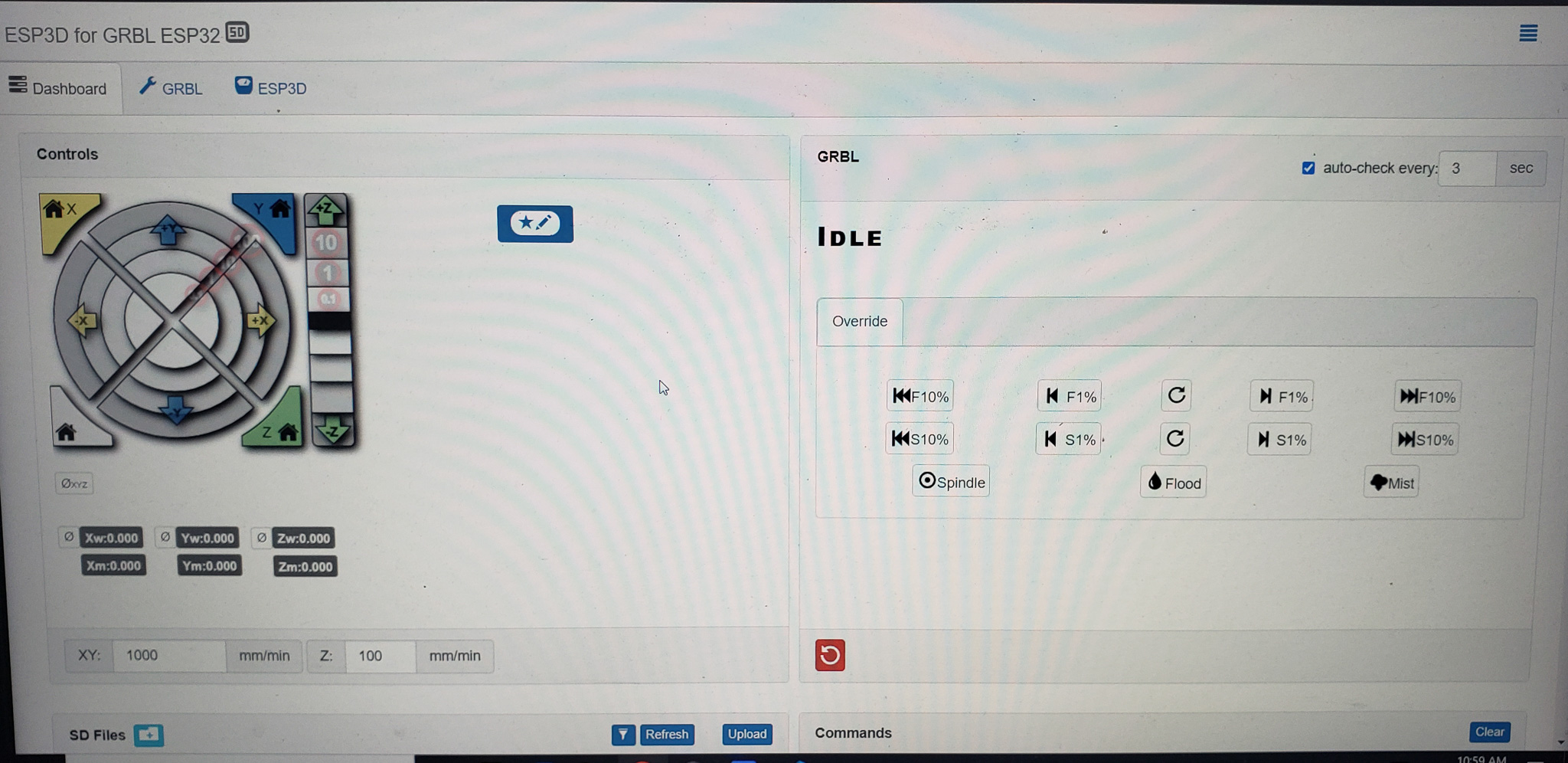
Third, the ESP32 option tackled two tasks at once. It served as both the “controller” and the “computer” in a single package. It even offered remote control via WiFi or Bluetooth, along with an onboard server providing a direct web interface for managing the machine. Plus, it allowed for any other form of external control, if needed.
The more I read about FluidNC, the more I liked it. I had no shortage of ESP32 boards of various versions scattered around my drawers — I didn’t even need to get out of my chair. Before I even finished reading the firmware’s wiki, it was already up and running:
Completely plug-and-play, “one click,” just as I’d hoped.
Outcome of the Preparatory Stage:
Hardware: Check.
Fasteners: Check.
Control Block: Conditionally present.
Auxiliary electronic components (e.g., buttons and wires): Partially available, with the rest easy to acquire.
The only major purchases left were new motors and a spindle. But there was no work involved there — just an online order and waiting for delivery to the doorstep. After that, it would simply be a matter of bolting them into place.
My Friend involved in the project — the same one who had been pestering me about this machine for years — volunteered to take on the task of manufacturing the motherboard for the controller and the necessary modules. First, he meticulously checked all the schematics for errors and overall feasibility. The idea was that by the time he completed the electrical portion of the project, I would have finished restoring the mechanical part. Then, it would just be a matter of plugging everything together… And, by and large, that’s exactly how things turned out.
With this setup, the project was given the “green light” by a majority vote in my head.