
“The fragmentation of objects in the world is merely a trial,
designed for us to unite them as one.”
— Satya-Sangama: The Essence of Unification
This will be a lengthy article, as this stage of the project involved assembling the entire mechanical structure of the machine — along with the accompanying basic electrical components. At first glance, it might seem like a straightforward task, given that by this point there was already a complete kit with all the necessary parts and fasteners. However, in reality, it turned out to be an endeavor where one could easily get bogged down for quite some time. Even painting the parts alone devoured almost three weeks.
And then there was the challenge of not just screwing everything together — but managing to do so accurately and aligned — overcoming all the flaws inherently present in the design. For instance, to ensure that a circle wouldn’t turn into an oval or that a rectangle wouldn’t end up as a trapezoid or some kind of parallelogram — heaven forbid, let’s not even speak of such horrors!

Painting parts before assembly is my least favorite process due to its incredible tediousness and duration — regardless of its form. Be it painting walls in a room or detailing a model tank on a desk. Quite often, I manage to offload this part of the work onto my Wife. But not this time…
For this project, I’ll lay out this personal nightmare as a sort of instruction manual, so that others, if the need arises, can fully experience the depths of despair, monotony, and hopelessness of this dismal routine.
Considering that, in this case, the “original” paint could only symbolically be called that, the first step requires nothing more than a simple metal scraper. With it, the “paint” can almost entirely be scraped off the parts, resembling dried-up mucus.
Next, the part is treated with sandpaper and a Scotch Brite “polishing sponge.” Among DIY enthusiasts, “Scotch-Brite” has become akin to the term “Xerox” — when a brand name turns into the name of a tool. It’s a fantastic thing to always have stocked in the workshop. It works not only on metal but also on wood… and practically anything you’d want to clean or polish:

All sorts of holes, nooks, and crannies are cleaned with acetone. The main thing is to avoid inhaling this stuff yourself. It’s preferable to wait for good weather and perform all these operations outdoors.
Afterward, the part is thoroughly washed in plain water with dish soap. A toothbrush and a regular green kitchen sponge will come in handy here. I have no brand preferences for these items. Whatever “shampoo” I can stealthily swipe from my wife’s kitchen works fine. The same goes for the green kitchen sponge.
The theft is most easily blamed on the Cat later. That’s his purpose in life. You can blame him for absolutely anything — from missing sponges to wood shavings all over the house. My Wife won’t scold him because “he’s got paws,” and he himself couldn’t care less. The perfect scapegoat! Tested and proven many times.
After several hours of drying, the part is rinsed in acetone once more. From this point on, it’s considered unacceptable to touch it with bare hands. Gloves only — no exceptions! Human hands are greasy. They leave that grease on everything they touch. It doesn’t matter what you think about this or how clean you believe your hands are. They’re still greasy. And this will inevitably show during painting. Don’t skimp on acetone and wipes!
As for the question, “Where did all the wipes in the house go again?” refer to the note above. By the way, don’t blame the Dog. Unlike the Cat, he cares! He’ll look at you with such sad reproach that you’ll want to die of shame…
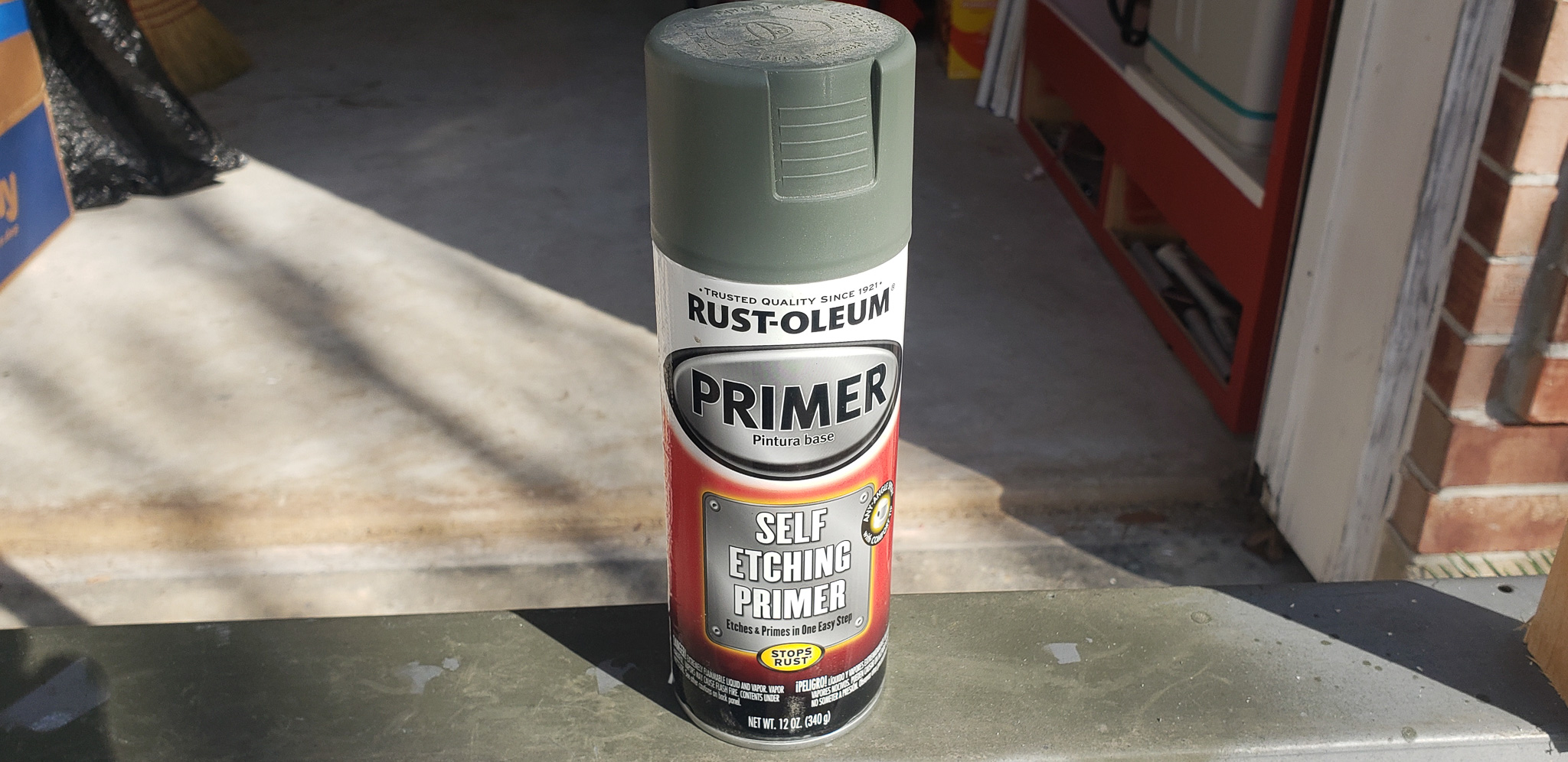
Aluminum is particularly tricky to paint due to its almost instantaneous surface oxidation. No matter how much you wash it with soap and acetone or protect it from greasy hands, everything will be in vain without a special primer. That’s why a self-etching primer was used to prepare the surface:

This primer had already proven itself in my 3D printer project. It still looks like new — no chips or peeling. This time, I also factored in the experience gained back then, making the process more deliberate.
The instructions claim that you can sand and paint over this primer after 20–30 minutes. Probably true. But — through my own experience and the recommendations of other DIY enthusiasts — it’s better to let this primer “set” on the part for at least a day. It’s like giving it time to calmly “eat” the oxide beneath and fully bond with the fresh, tasty aluminum.
I’ve tried both the method suggested online and the one recommended in the instructions. Subjectively, there does seem to be a difference. So now I stick to the “day-long” method from the internet. As for the actual reasons… Humidity and temperature definitely play a role. In our local climate, it might genuinely be necessary to follow a procedure different from the one recommended by the manufacturer.
What happens next depends on the circumstances. If I know the surface beneath the first layer of primer isn’t great, I carefully sand the primer using blocks with 600->800->1000 grit sandpaper. If the surface was initially smooth or doesn’t need to meet any specific “decorative” requirements, everything is lightly polished with the same Scotch-Brite sponge.
A second layer of self-etching primer is applied, thicker this time, but not so much that it starts to drip. Another day for drying (in my case, again).
After the second layer of primer, the final polish with a Scotch-Brite sponge is done, and the part is ready for paint. It’s applied in two, three, or four thin coats, with intervals of half an hour to two hours. Generally, for each subsequent coat of paint, the drying time of the previous coat increases by half an hour. That is, 30 minutes after the first coat, an hour after the second, an hour and a half after the third, and so on.
Of course, this depends on the type of paint, its brand, and specific properties, but I’ve developed this general rule through experience, specifically for Krylon paints, which I use most often.
Whether to polish each layer or not depends on your preference. If you want a “mirror-like” finish, polish it. If you’re after a “textured” look, don’t polish it. The thinner and more even each coat is, the better the results.
Oh, and one more thing… At all stages, protect the part from direct sunlight. This is crucial! I forgot about it again, and on a couple of parts, the paint “boiled” before it even began to dry… Although, why put it in quotes? It really does boil in our sunlight… In short, I had to strip everything and repaint. Which didn’t make the process any more fun, not in the slightest…
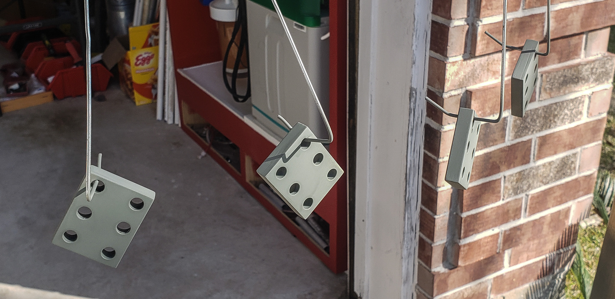
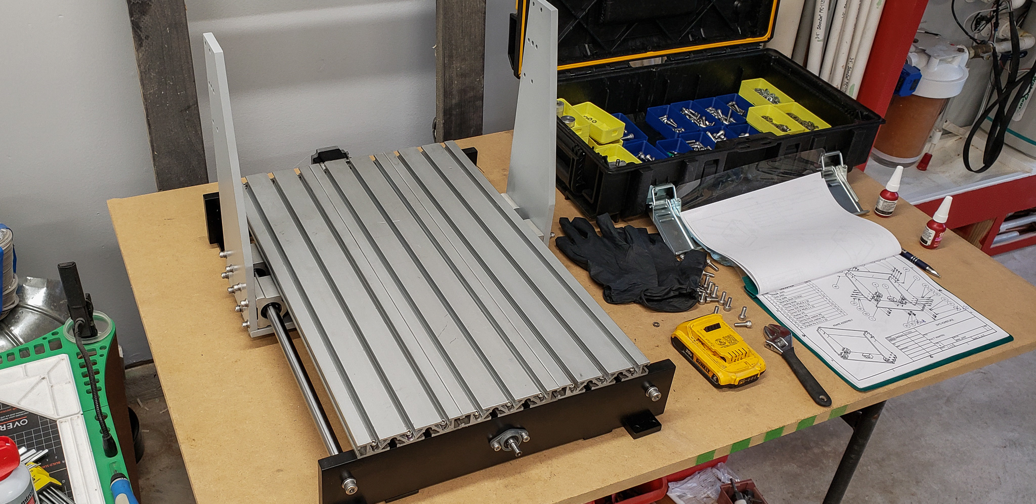
Finally, after receiving the complete set of painted parts and bidding a final farewell to my nervous system, I reached the much-anticipated assembly phase, which was meant to compensate for all the utter monotony of the painting stage.
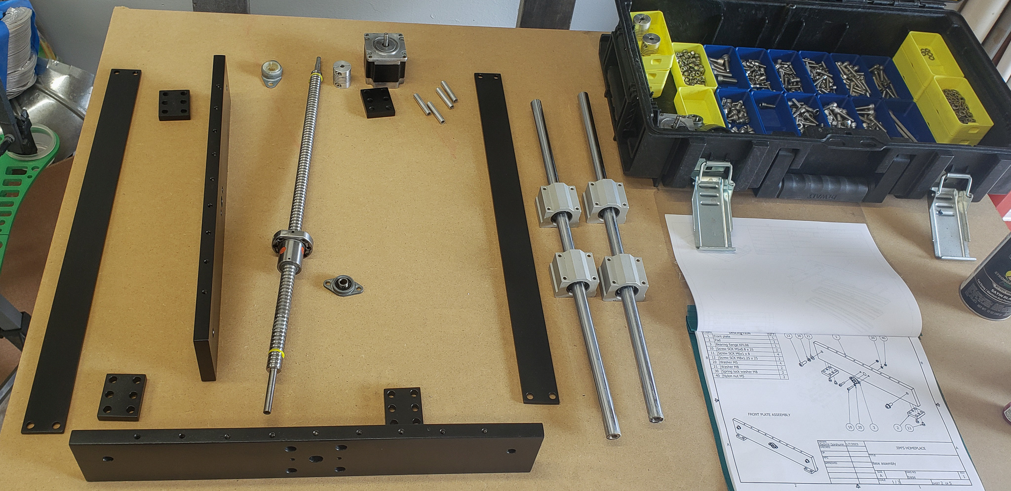
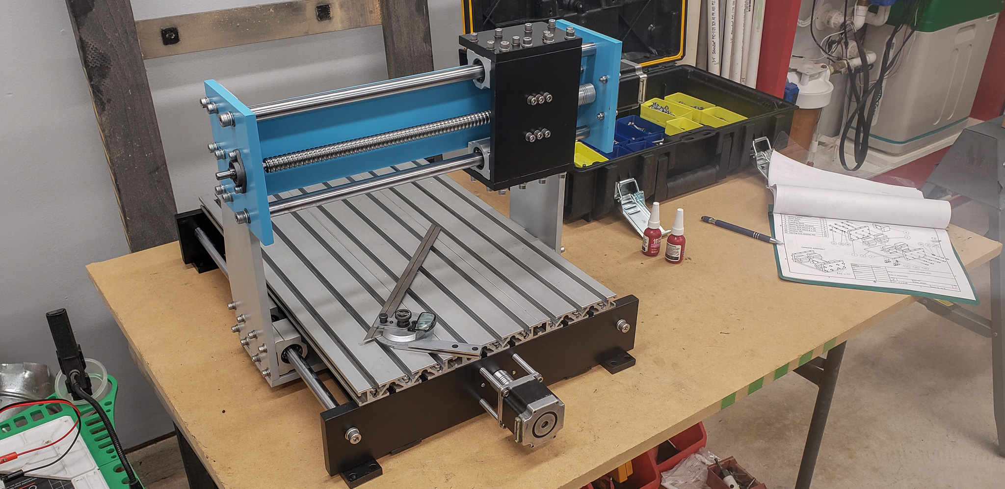
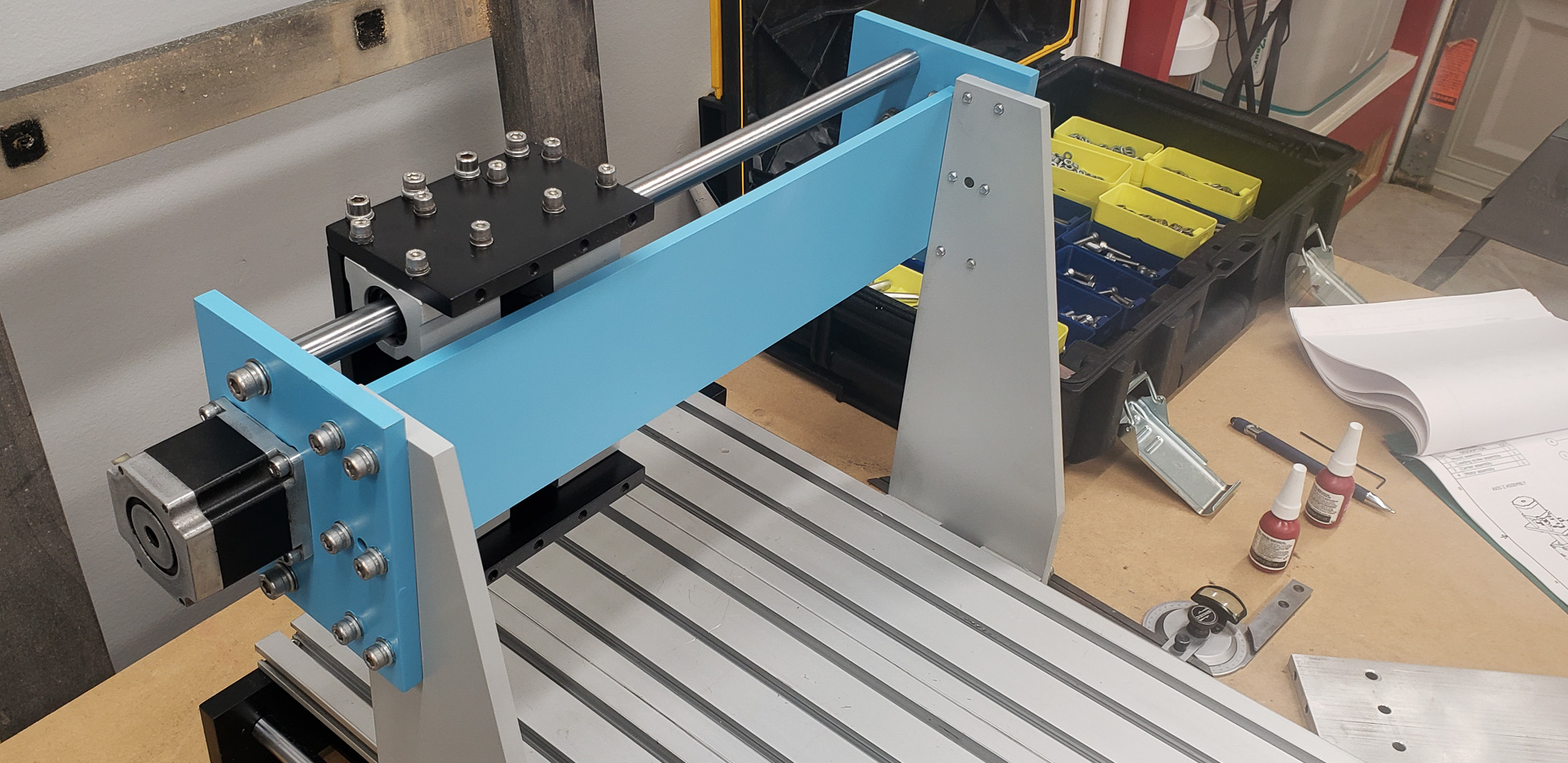
As always, there isn’t much to say about the most enjoyable stage. The parts were simply put together and bolted into place:

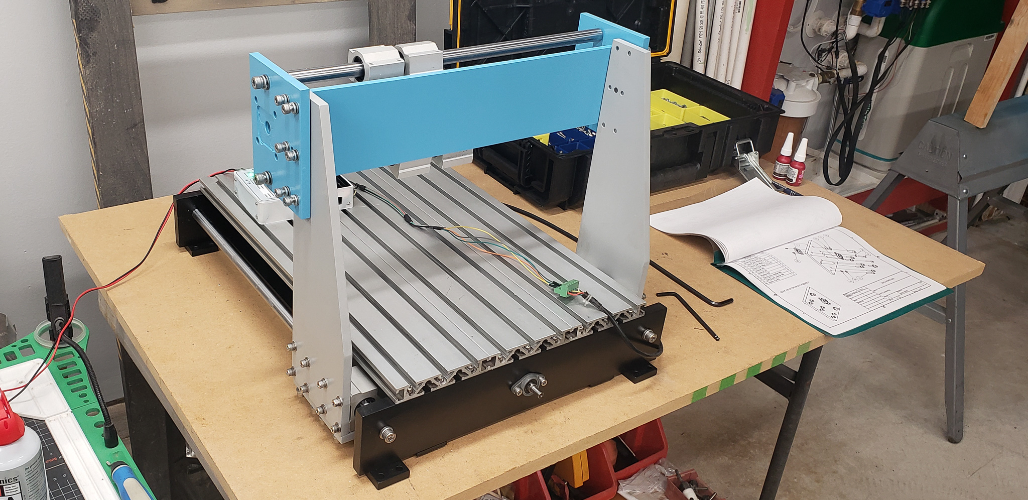
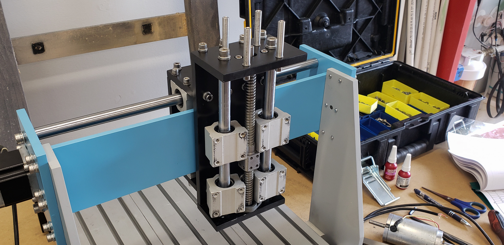
Most of the fasteners were paired with split lock washers. Where split lock washers were unsuitable, the threads were secured with 222 Loctite (for areas requiring higher stability, 242 Loctite was used). When a nut was used, it was always a nylon lock nut. In theory, no vibrations should bother this machine now.
By the way, the color scheme for the parts was copied exactly from my favorite “Dusya” (see the first part of this series). I have no regrets. It turned out to be a cheerful and neat device, rather than yet another black monstrosity.
The initial assembly went smoothly, and it was time to move on to the next steps.
Ideally, this stage should have included installing the new motors. However, they arrived much later. As a temporary solution, the machine was fitted with its old motors.
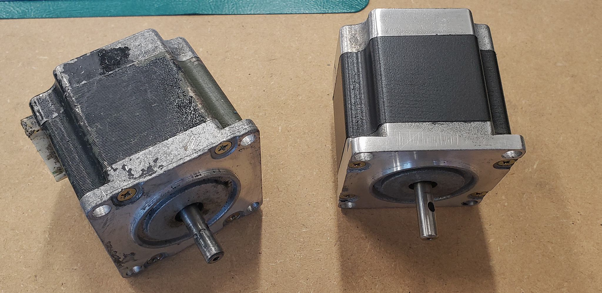
Surprisingly, the old motors turned out to be quite functional. I even took the time to clean off the stubborn paint and restore them (on the right — slightly cleaned; on the left — fully restored):
I even managed to control them without the control unit.
Back during the construction of the 3D printer, I had put together a kind of “universal stepper motor driver.” A little box with the grandiose name “Elite eXtreme” (don’t ask why…):
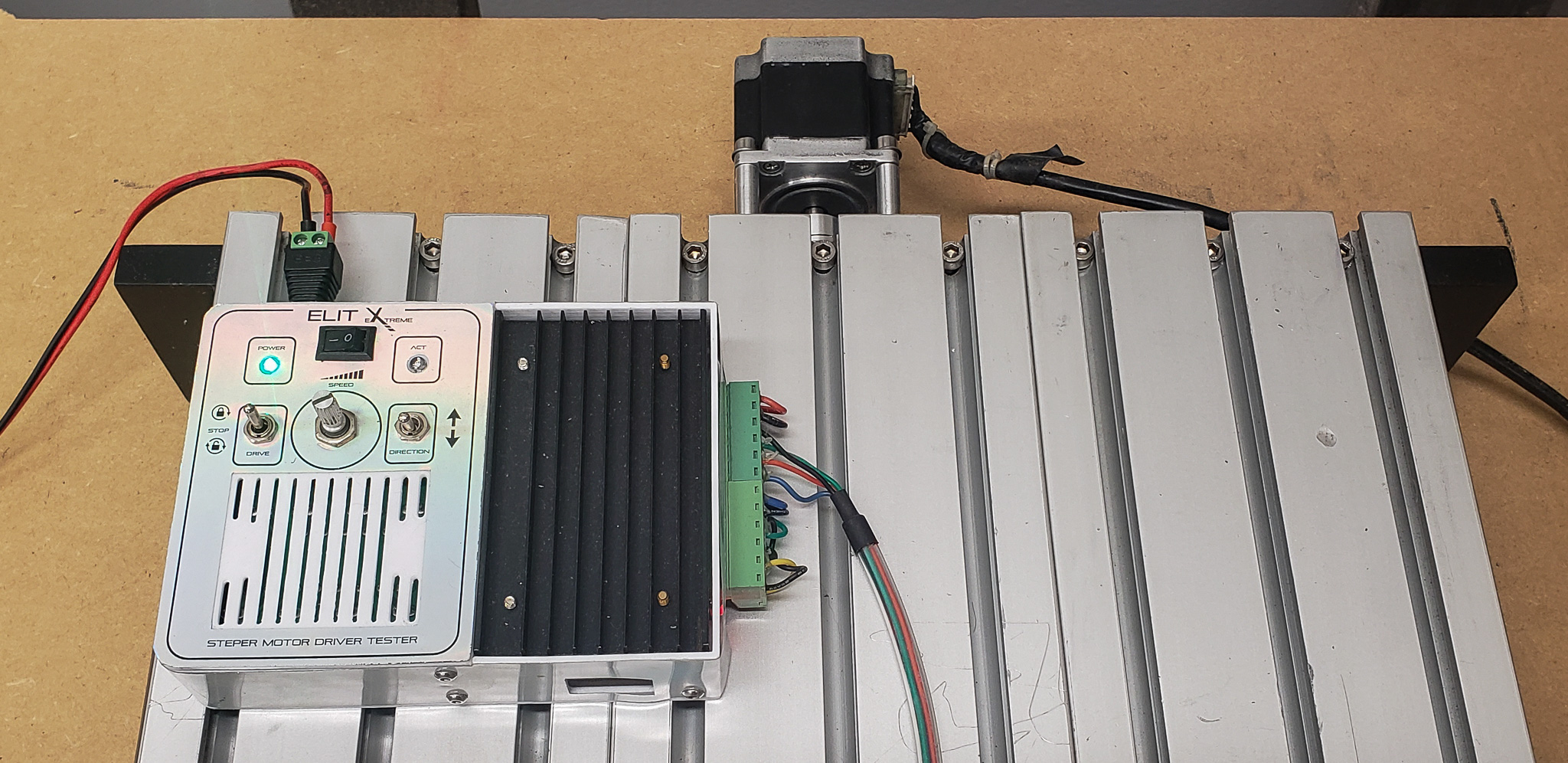
It can drive a motor forward or backward and adjust the speed. Settings include selecting the required current power and the number of steps per revolution. This allows it to be connected to a fairly wide range of stepper motors.
There’s no separate article about it, as there’s not much to write: an Arduino + a cheap external motor driver + a couple of switches + a couple of indicator lights + a three-line firmware. Nothing extraordinary, but it has saved me on multiple occasions and has earned its place in the lineup of “useful tools that should always be on hand.” Now it lives on the shelf above my desk, alongside the “Resisting Mantis” — within arm’s reach.
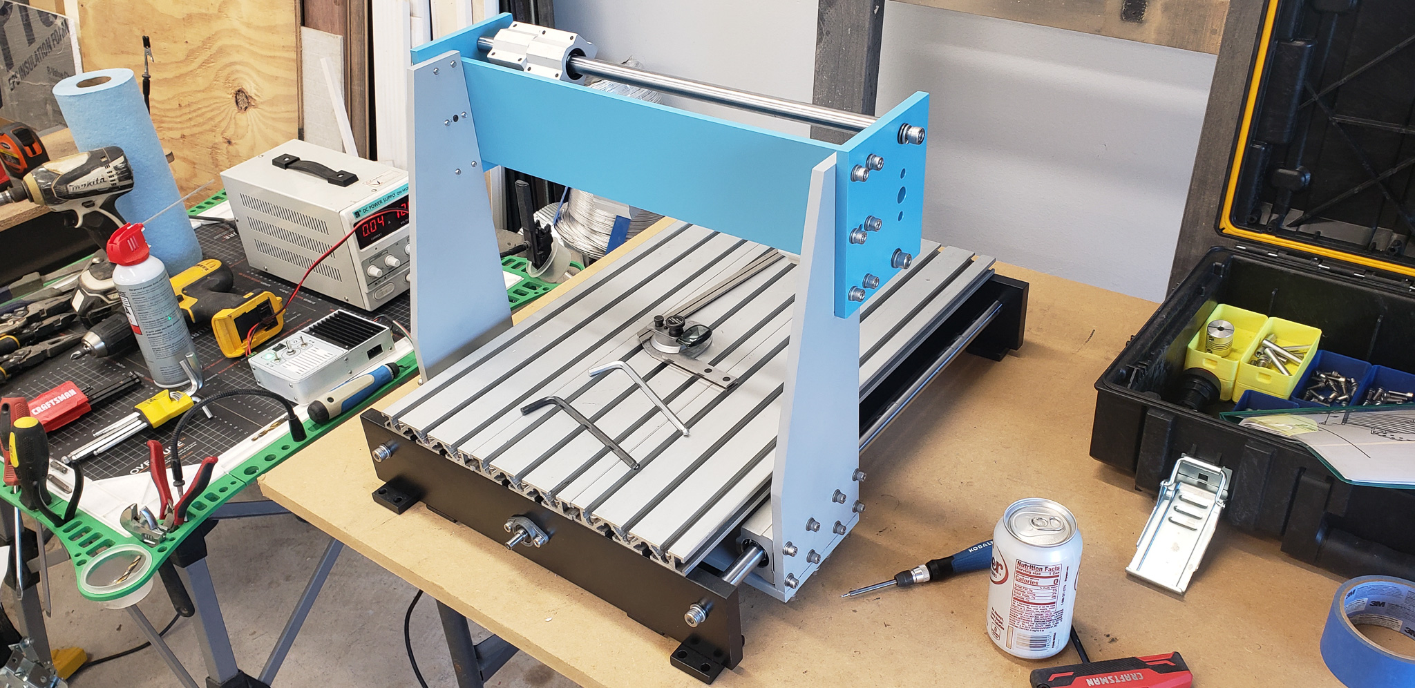
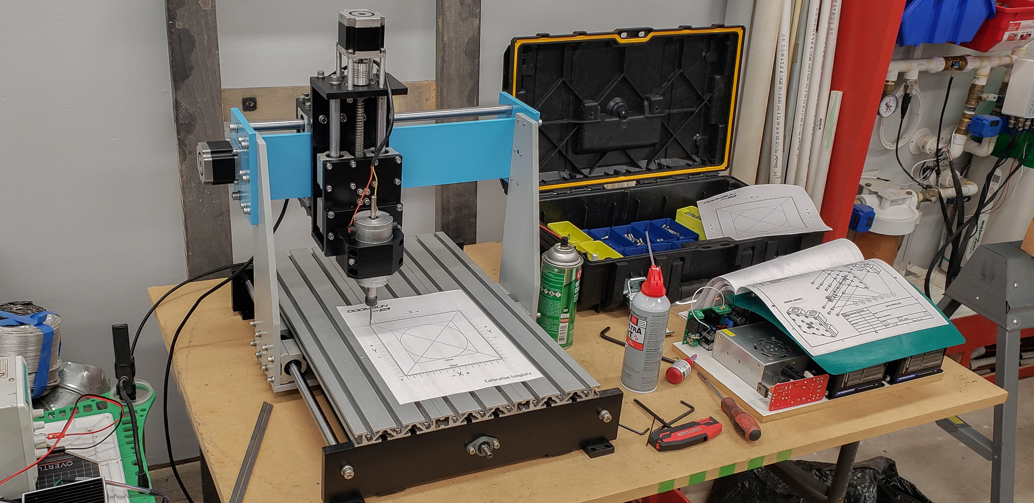
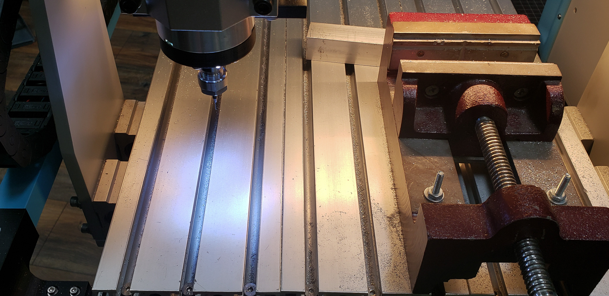
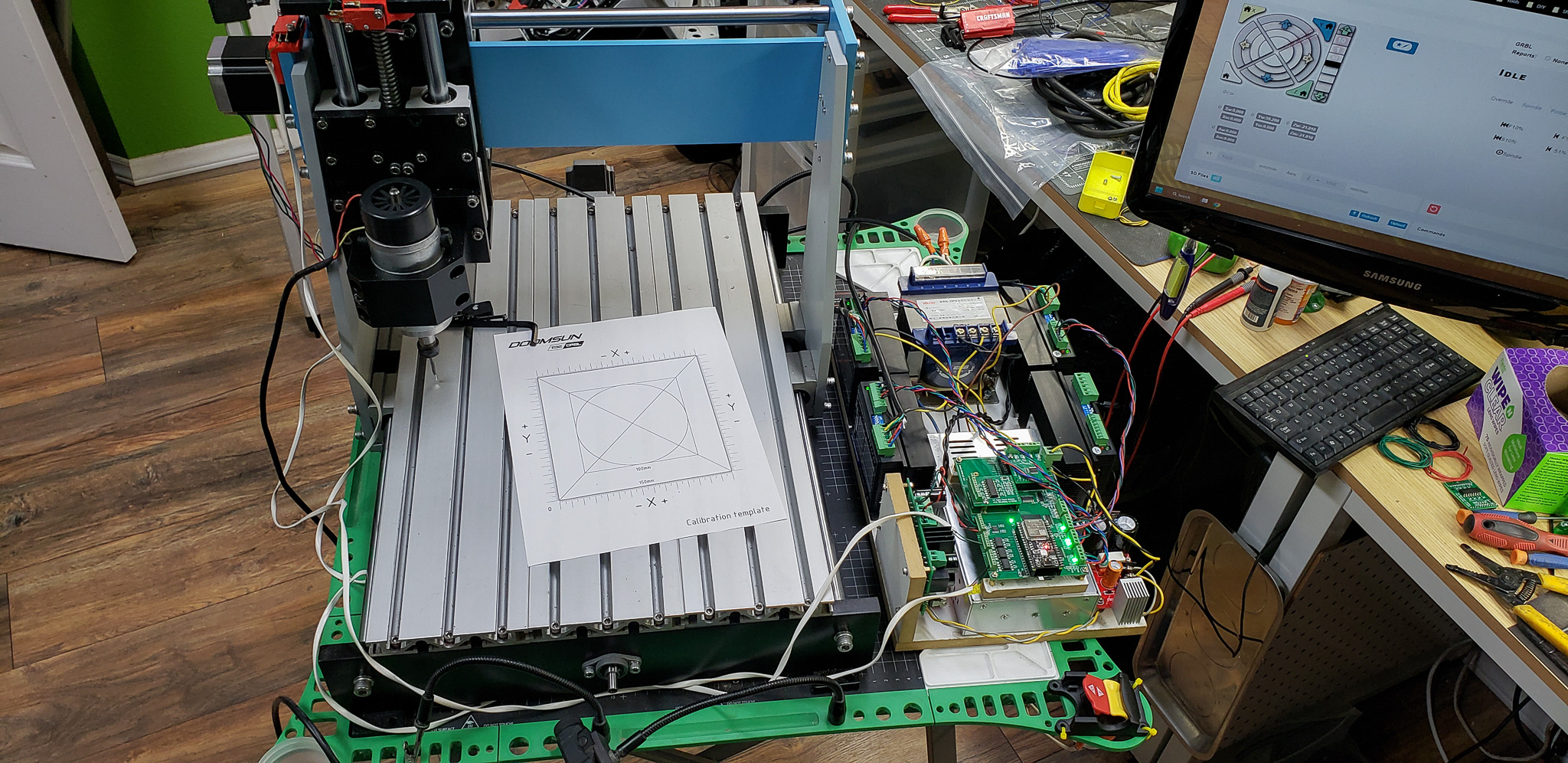
Using this magical little box, the focus during assembly was not so much on kinematics per se, but rather on verifying alignment, parallelism, and perpendicularity of movements along all axes:

When, right after assembly — without any fine-tuning or bolt-tightening — the marker hit all corners of a template square, it became clear that this whole endeavor might actually amount to something, and all the prior struggles to correct misaligned parts were worth it. The discrepancy was about 0.1 mm, which was quickly corrected by tightening a couple of bolts in the frame.
The circular test was postponed until the control unit arrived, as the magical box can only control one motor at a time, and you can’t draw a circle with just one motor.
In addition to hardware, the machine gradually acquired various auxiliary components — including ones it never had before.
For example, limit switches. Oddly enough, the original version of this machine wasn’t equipped with limit switches at all. This meant it couldn’t automatically home itself to a “home” position, nor did it have any safeguards against exceeding the working area due to errors.
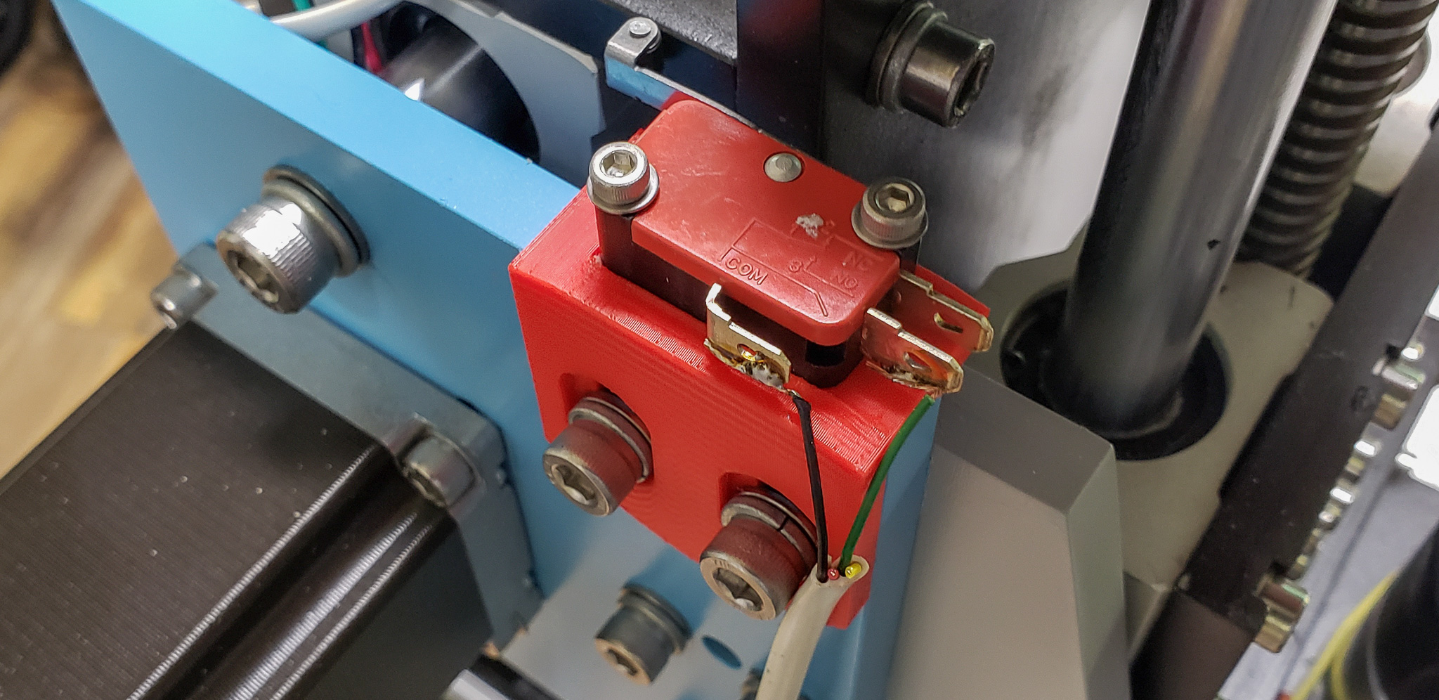
Standard micro switches were used as limit switches.

I have plenty of them, and they have their own story! But I’m not going to share it… If I were to tell the story behind every single nut and bolt, this series of articles would never end. Almost every part I’ve salvaged has its own history — like the bricks for Uncle Pumpkin’s house.
“This is the very brick I got ten years ago for Christmas,” Uncle Pumpkin would recall, picking up one of the bricks and stroking it like a kitten. “I bought it with the money I’d saved for a holiday chicken.”
Why micro switches instead of optical, inductive, or any other modern alternatives? Well, I must admit I caved to the opinion of the “general public.” In their blogs and YouTube channels, people strongly advised against using progressive modern limit switches for “metallic” CNC machines. They claim optical switches can be triggered by stray chips flying into their sensor area, or they can go haywire due to the presence of a nearby metal workpiece, or they simply fail to withstand vibrations. The consensus seems to be that a simple micro switch is the best option — no need to overcomplicate things.
I personally have no experience comparing different types of limit switches in this context. However, the arguments presented seemed reasonable to me, and I couldn’t come up with any counterarguments off the bat. So, I didn’t overthink it and used the stockpile of micro switches I already had.
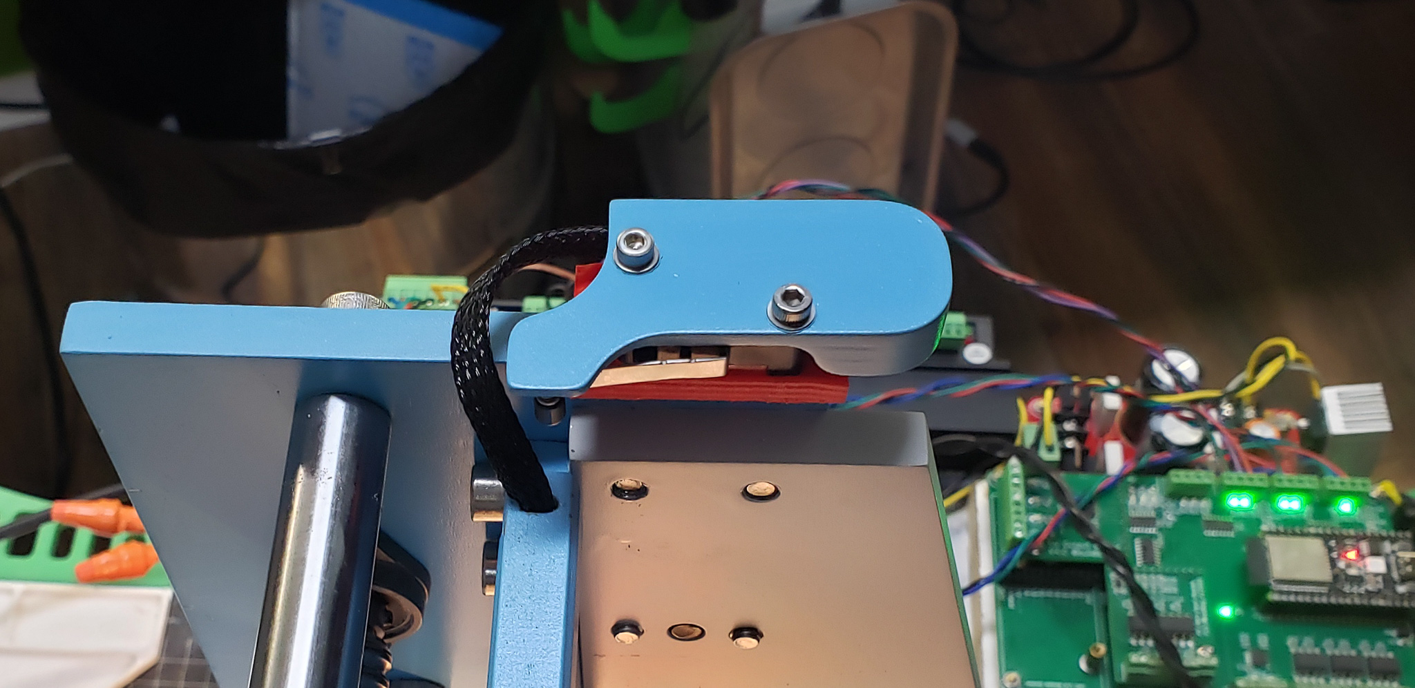
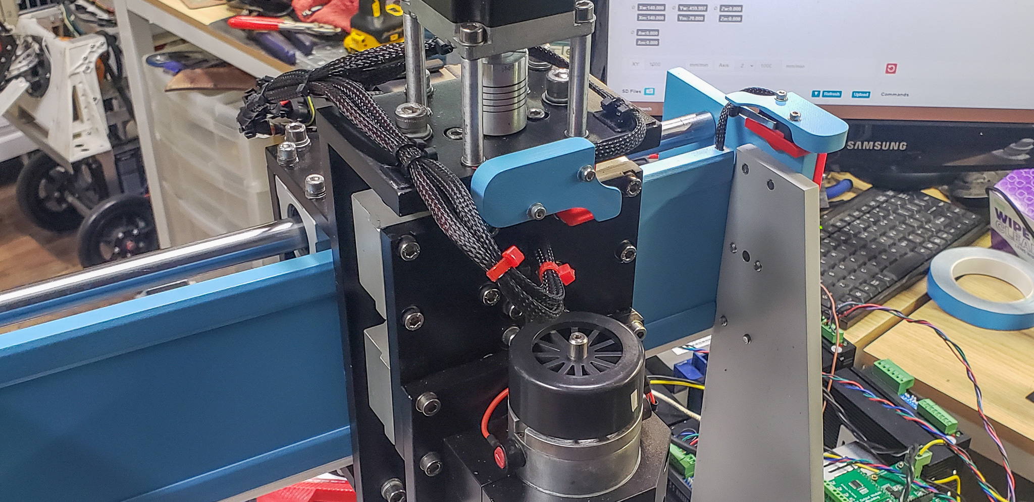
Later on, special covers were made to protect the sensitive parts of the limit switches:
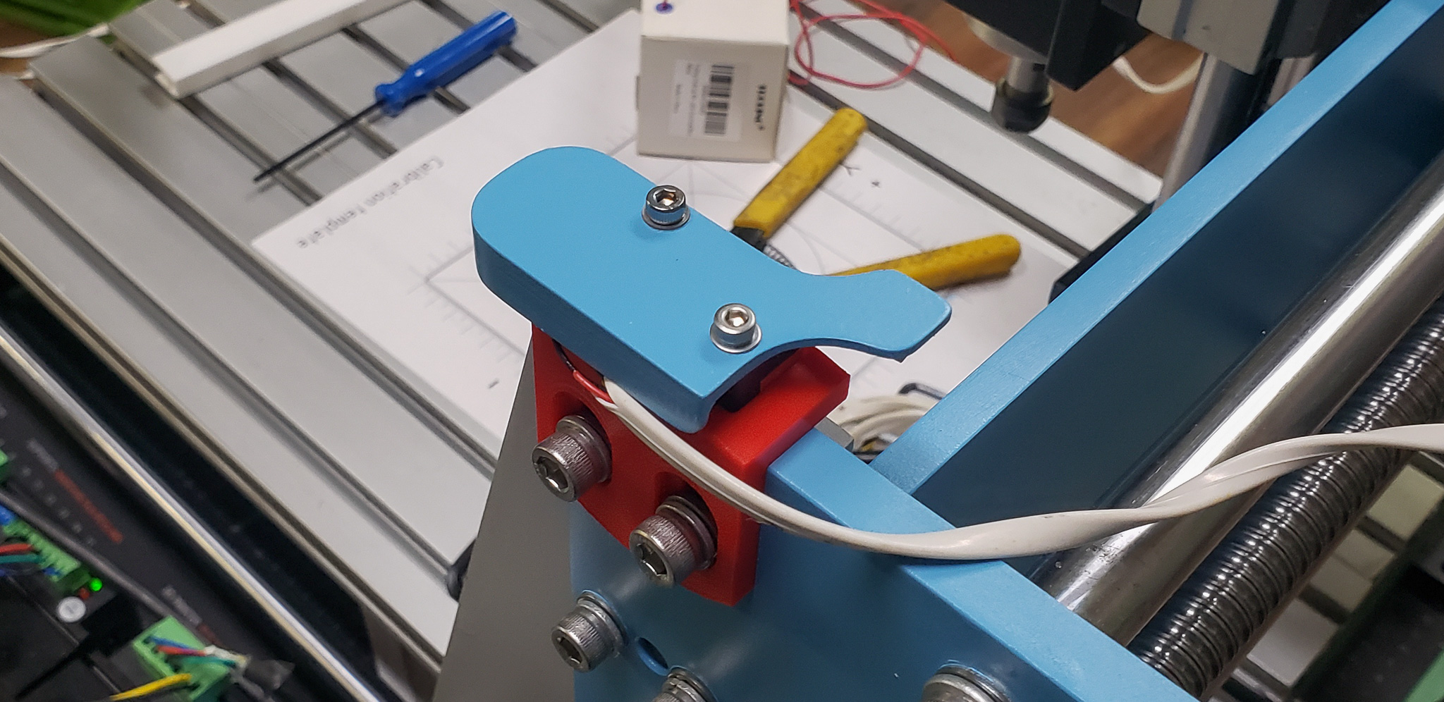
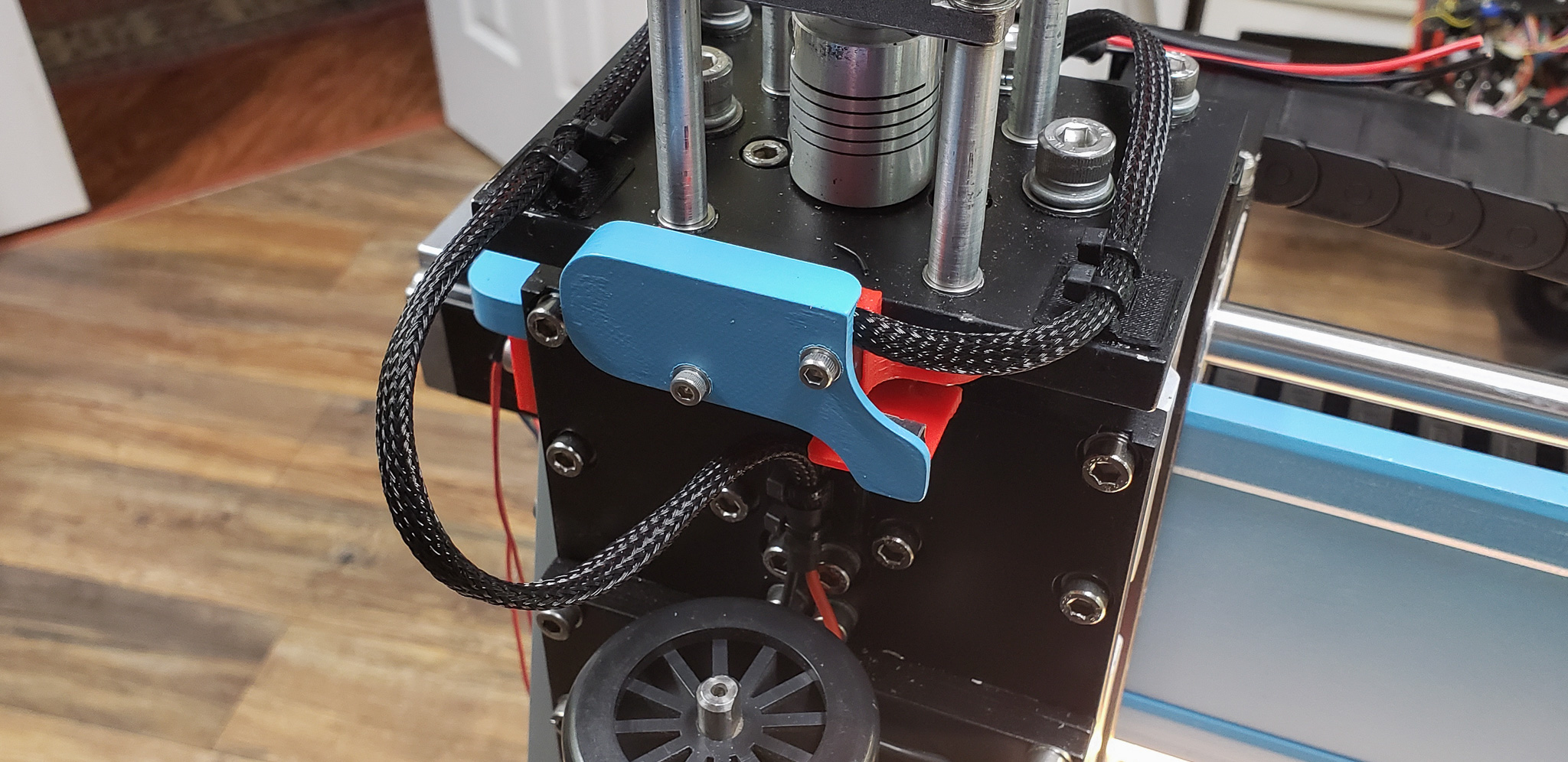
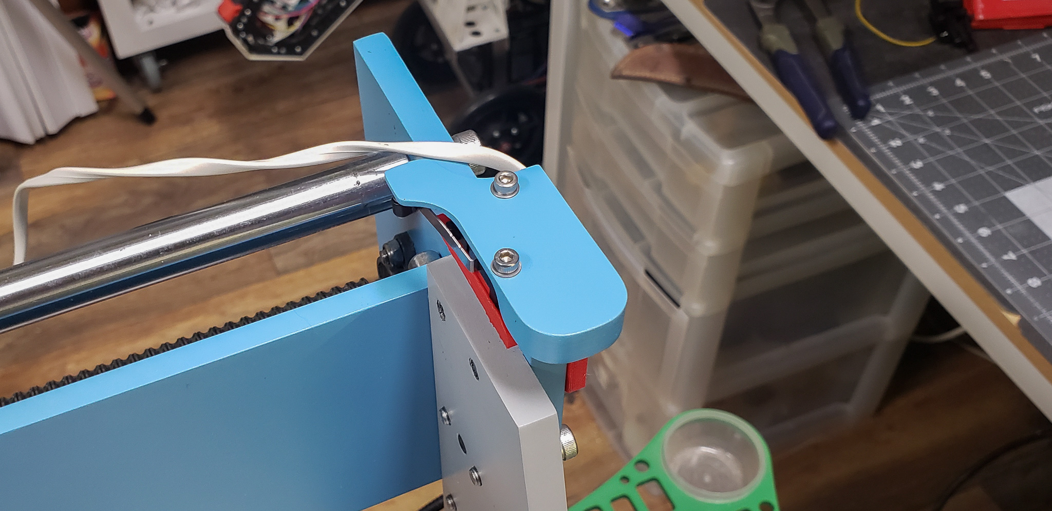
These covers were designed not only to shield the switches but also to prevent accidental triggers.
Since some auxiliary components were missing from the original design, as mentioned earlier, they had to be developed from scratch. No matter how thoroughly you model them in advance or test-fit them on a computer screen, there’s always a chance something won’t align properly. Having a 3D printer significantly simplifies this task, as it allows you to first print a prototype, test-fit it in place, make any necessary adjustments, and then print the final, accurate part.

Prototypes for various mounts, holders, supports, and so on were printed using red filament. This served as a visual reminder to later reprint them in proper quality using black filament, should they fit correctly on the first try.
For prototypes, I use a print mode with “one top/bottom layer, two perimeters, 10% infill, 0.24–0.28 mm layer height.” This, naturally, results in a noticeable boost in printing speed. In just 10–15 minutes, you can have something to check for hole alignment and dimensions. However, such a part will be mechanically very weak compared to a final print with “three top/bottom layers, three perimeters, 35% infill, 0.16–0.20 mm layer height.” Thus, all prototypes must be replaced with proper parts; otherwise, they won’t last long.
Interestingly, in some cases, the seemingly out-of-place red color unexpectedly turned out to be quite useful, despite not matching the machine’s color scheme. As a result, certain components were deliberately printed in red filament for their final version. This included, for example, the mounts for the very same limit switches. The red color immediately signals that this is a sensitive part of the system, encouraging one to instinctively handle that area with extra care — keeping it clean, avoiding damage, and generally paying heightened attention to the component.
The cherry on top of the auxiliary components was the lighting. After all, what machine is complete without it?
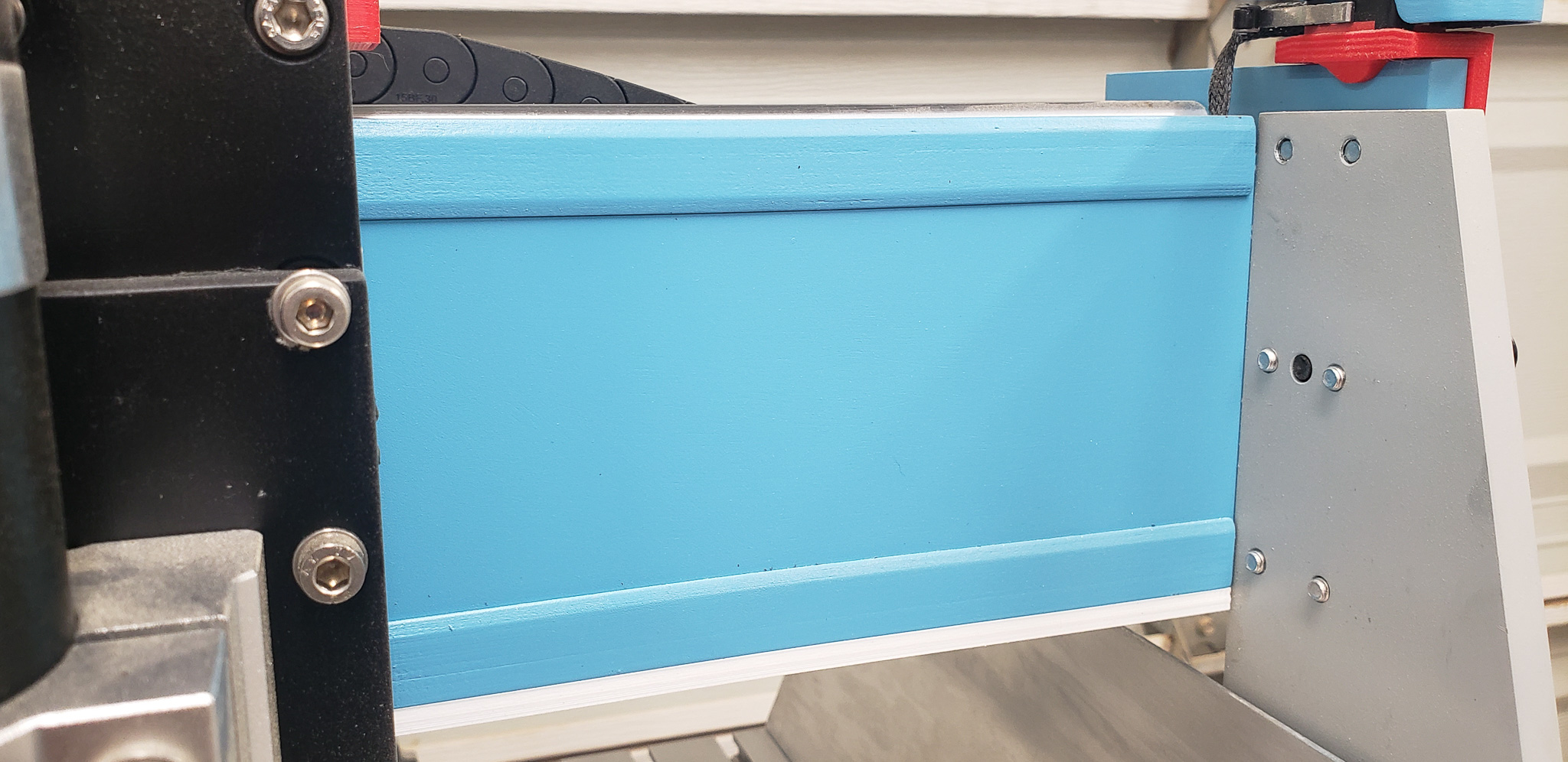
To implement this, I had to modify the overall design of the gantry in the following section:

- Top Cover
- Aluminum Base of the Gantry’s Horizontal Beam
- Bottom Cover
- What we can conditionally call a “lampshade,” which also functions as a diffuser for the light sources.
- LED Strip
The primary purpose of covers 1 and 3 is to act as channels for routing wires from the limit switches and other auxiliary components. These wires are hidden inside when connections need to be run across the machine along the horizontal beam:
Additionally, the bottom cover includes an attached diffuser with an LED strip:
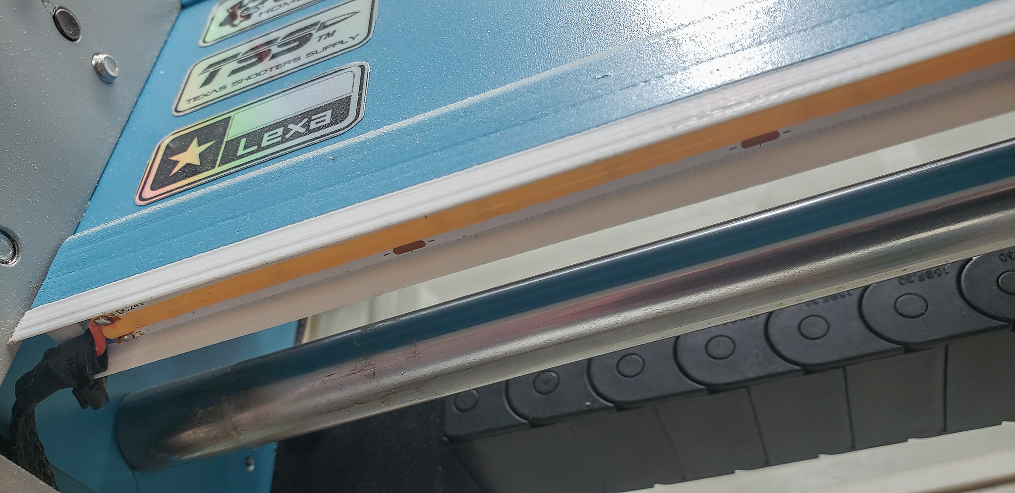
This setup ensures that there’s no stray “spaghetti” of wires within the machine’s workspace that could get caught in the cutting tool or interfere with the workpiece. At the same time, it provides some background lighting:
However, this is only ambient lighting! It’s more for aesthetics and ambiance, with little practical necessity.
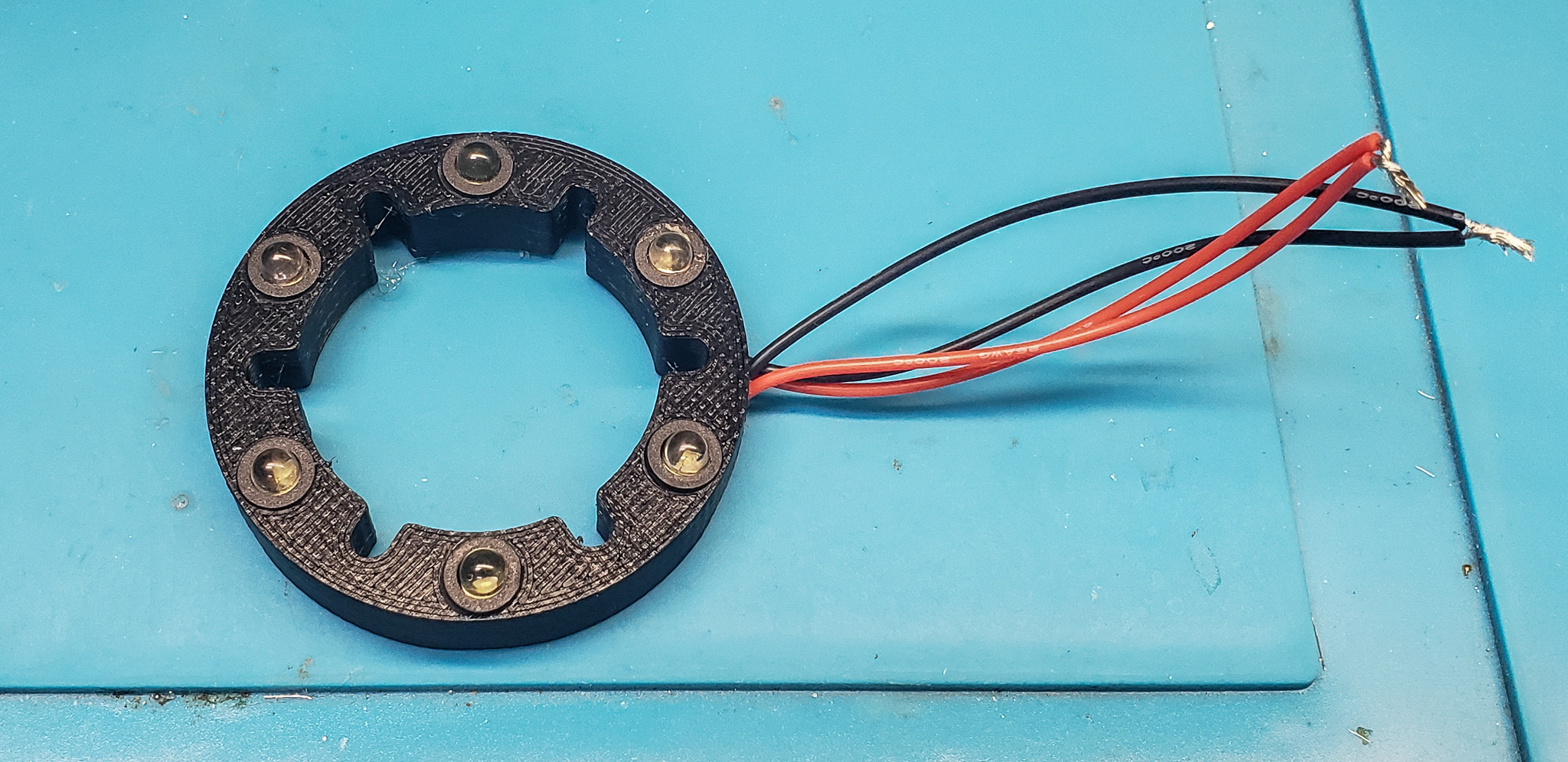
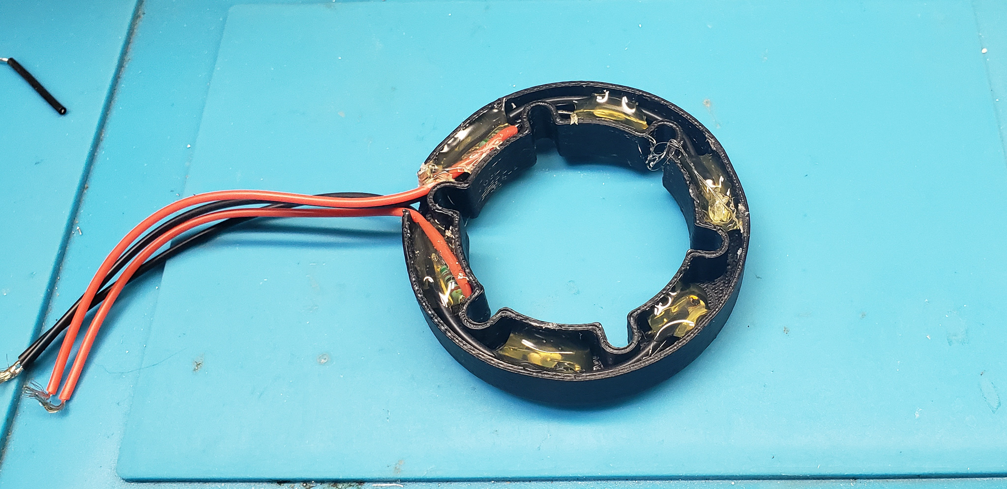
On the other hand, lighting on the spindle is entirely justified. No matter how well-lit the workshop is, the machine’s own components cast shadows within the working area. To see more, better, and further, additional lighting is essential in the workspace:
This was kept as simple as possible, using six standard bright white LEDs:

Naturally, all these additional components (lighting, limit switches, brackets, covers, etc.) were simultaneously incorporated into the overall model and drawings, becoming an integral part of the project at the level of full documentation.
Many assembly operations were carried out simultaneously, so in the photos, the machine appears sometimes with the old motors, sometimes with the new ones, sometimes with the old spindle, and sometimes with the new one. In this article, I find it more convenient to group events by topic rather than the sequence of operations.
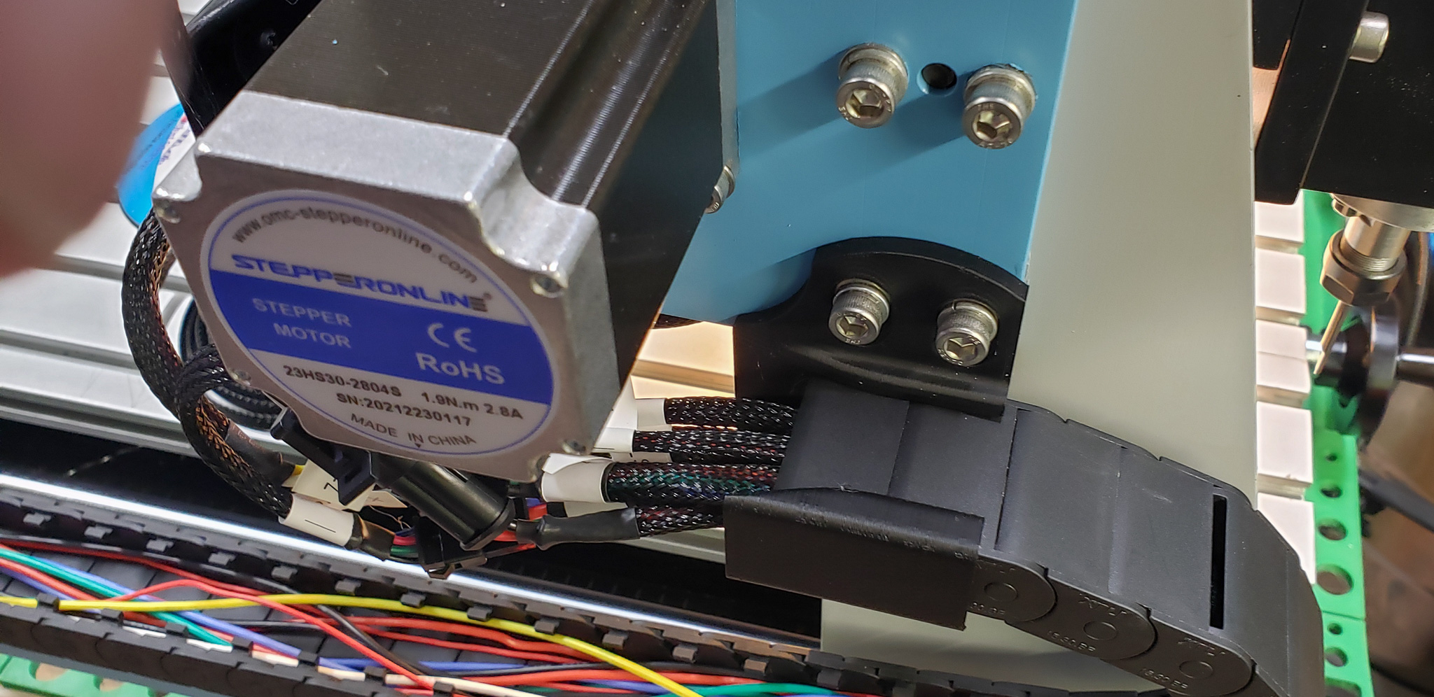
To add to the confusion, various adventures disrupted the process. For example, installing the new motors triggered an unforeseen incident (photo below: the “long” one is new, and the “short” one is old, for comparison):
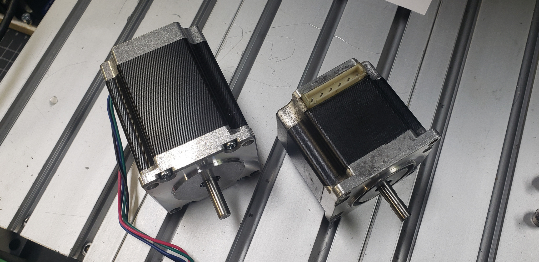
The new motors are Nema 23, 2.8A, 269 oz.in. The old ones were also Nema 23 but were so ancient that I couldn’t find their specifications. However, they were significantly weaker — that much is certain.
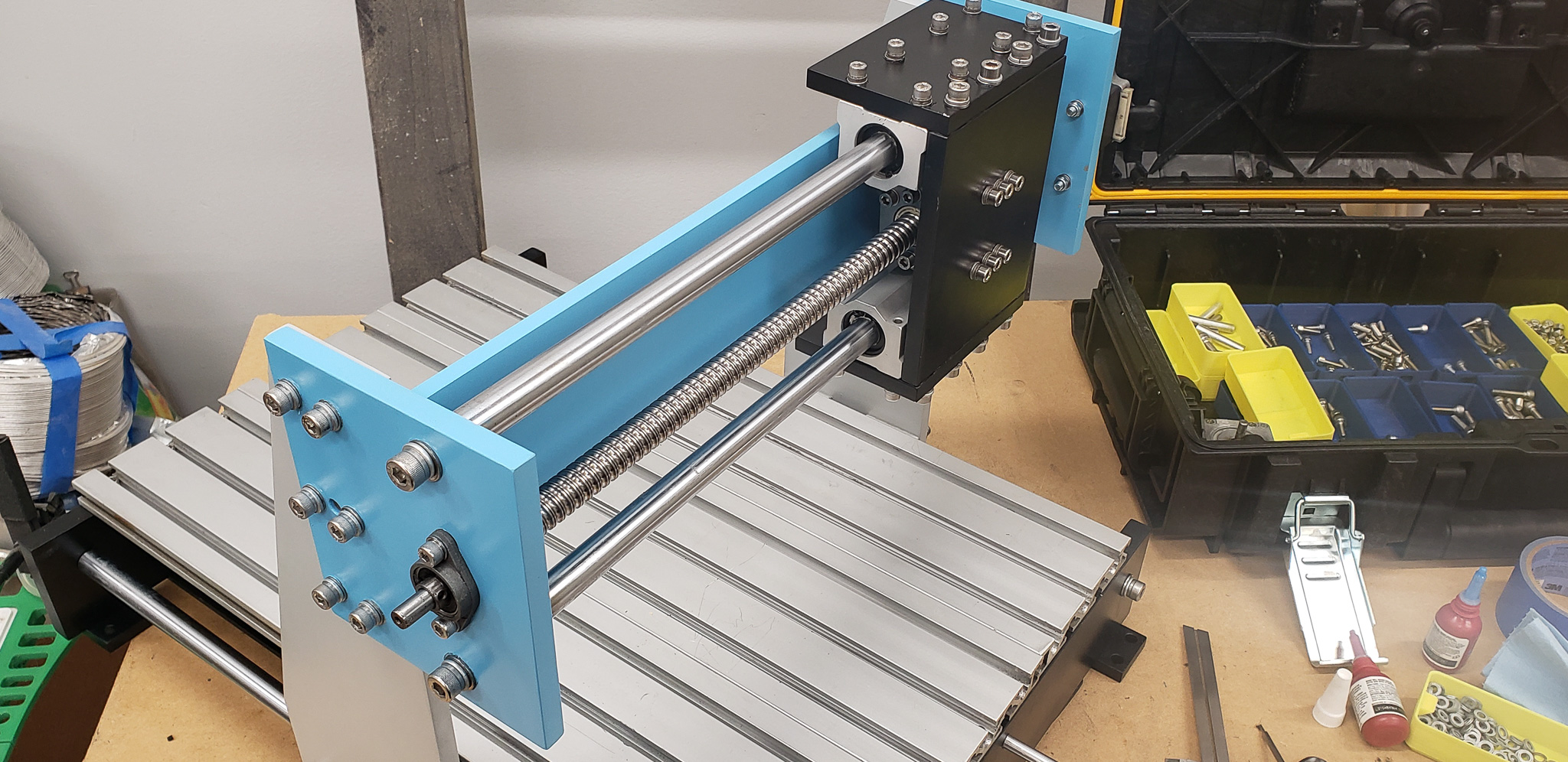
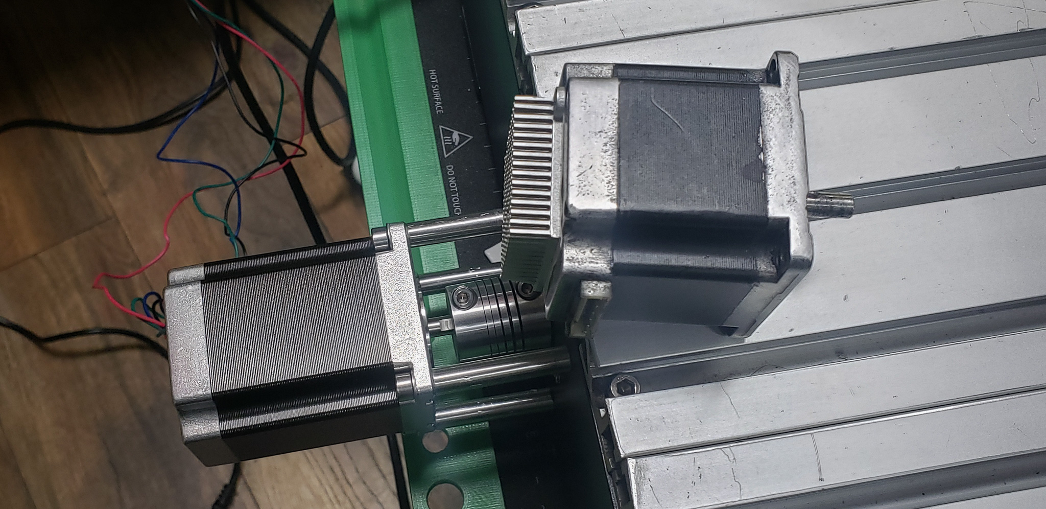
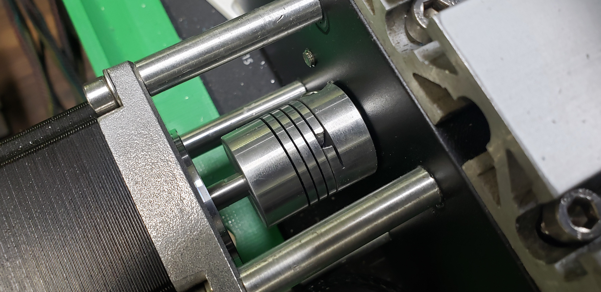
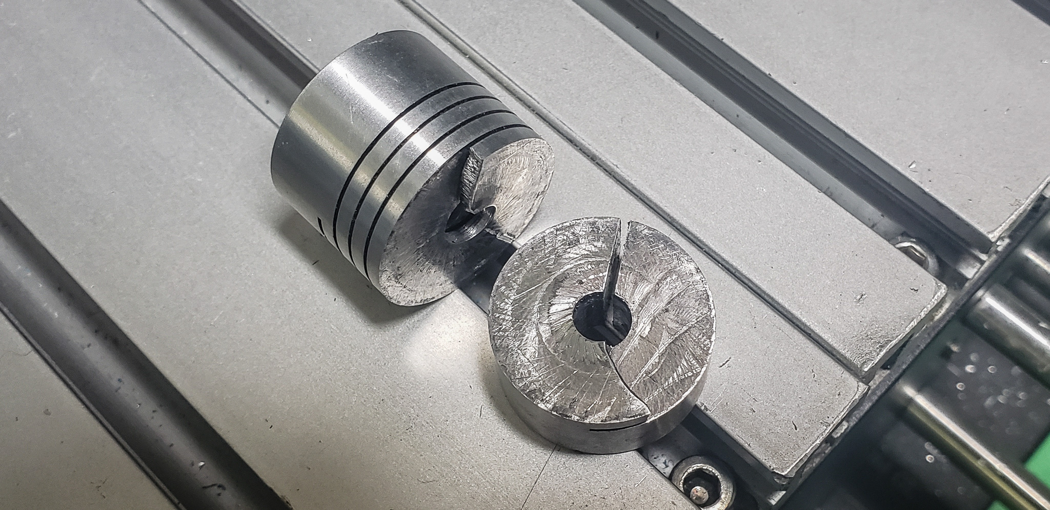
I discovered this during a test run of the Y-axis when the new motor, without any smooth acceleration (since the controller wasn’t in place yet), went full throttle with such torque that it outright broke the coupling connecting it to the worm gear:
To prevent similar incidents in the future, I had to replace all the couplings with more robust ones — membrane couplings:
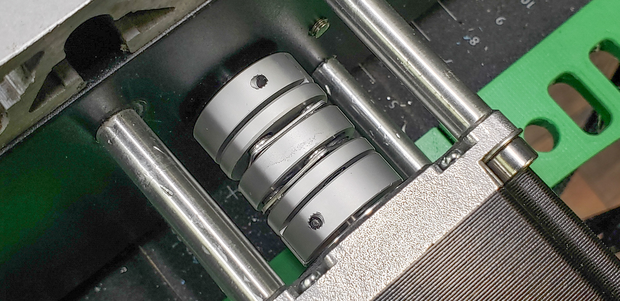
These do everything exactly the same as standard “spiral” couplings but can withstand significantly higher loads. Overall, they are also much more durable.
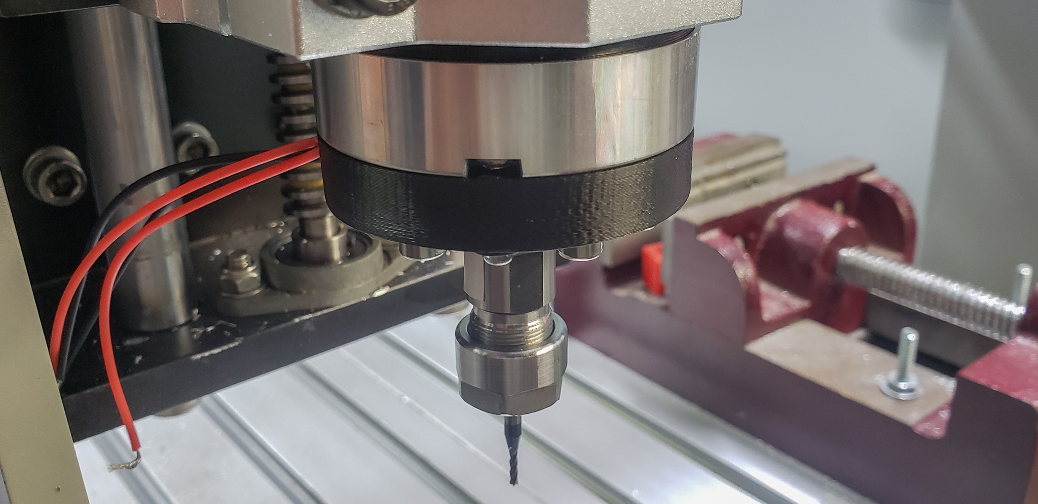
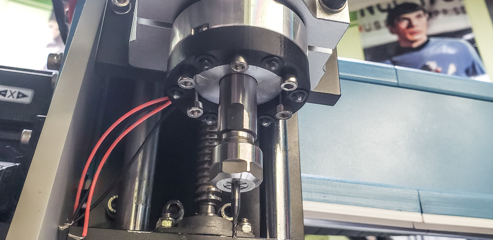
The spindle was also replaced at some point during the process.
The updated machine produced its first bzzzz sounds using its original spindle. This spindle had been restored, cleaned, lubricated, and even fitted with new brushes:
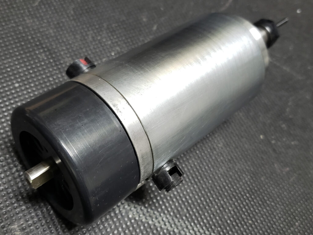
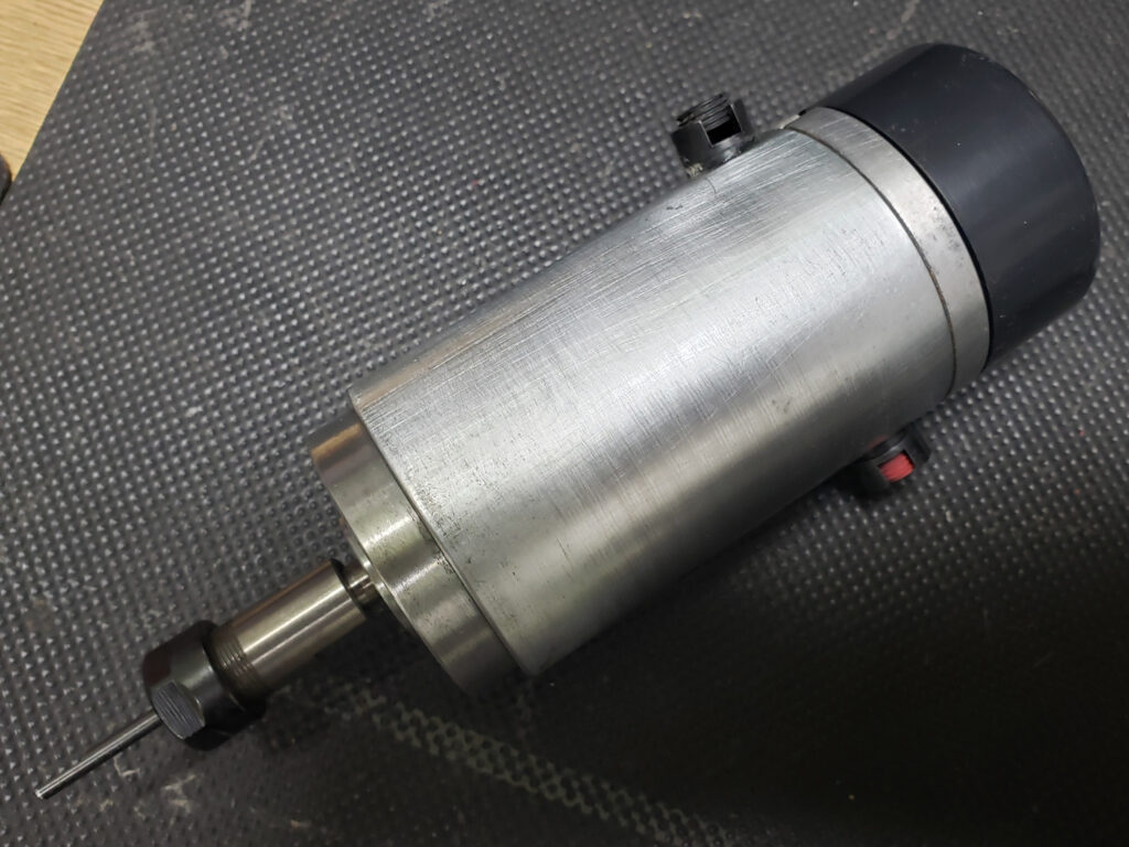
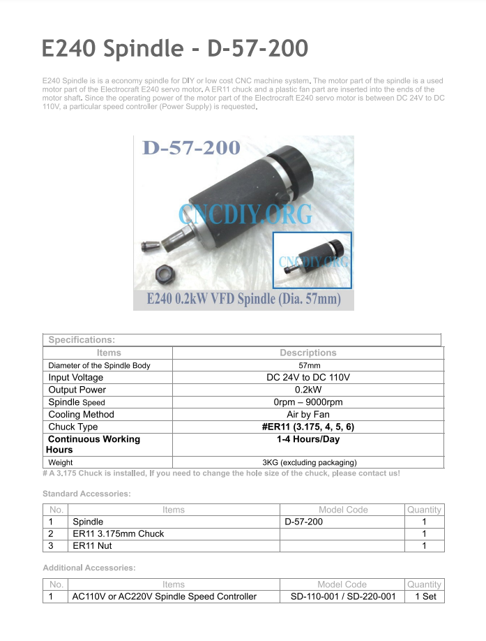
It’s a decent motor, in principle, if you overlook its power supply requirements. I even managed to dig up something resembling a datasheet for it:
It’s not very suitable for milling, but it works well enough for light engraving. I’ve put it aside in storage — it might come in handy someday.
On active duty, it was replaced by a new spindle, about three times more powerful and equipped with a full suite of accessories and mounting hardware:
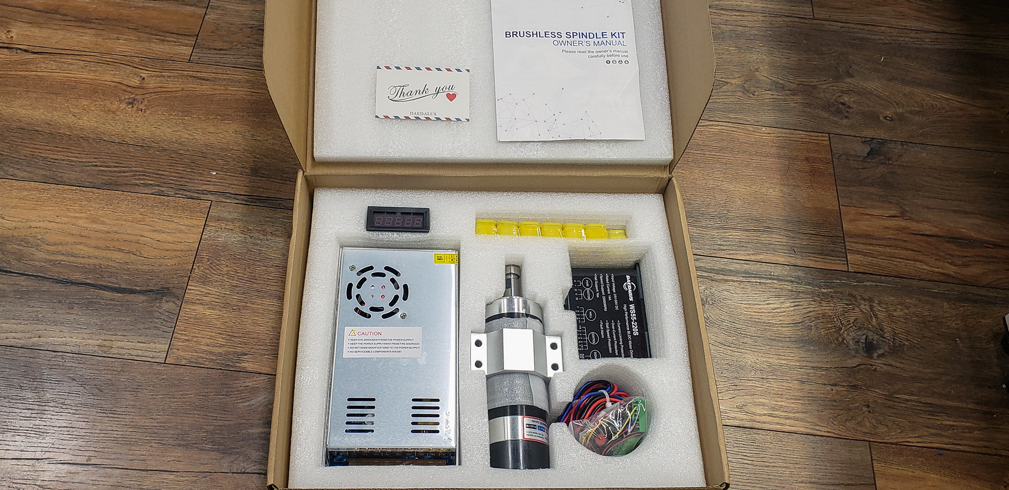

Daedalus is considered a decent brand in this weight class (under one kilowatt). We’ll see how it performs…
A note from the future:
We’ve tested it. For its price, power, and RPM — it’s quite solid. No miracles, of course, but it delivers what was promised and what was expected. It cuts aluminum with reasonable confidence. It could use more RPM, but for now, we’ll work with what we have. In any case, it’s leagues ahead of what was originally installed.
When it comes to wiring, a CNC mill is no different from a 3D printer — both are more about “the science of wires” than mechanics. There are a lot of wires. Just an overwhelming number! At first glance, you’d think: three motors and a spindle, no big deal. But then you add five limit switches (two for X and Y axes, one for Z), lighting, probes (which I’ll explain later), camera connections, and so on. Some components need 12 volts, others 24 volts, and yet others 5 volts. And the list keeps growing…
Fortunately, I knew what I was getting into. That’s why I immediately designed spacious, flexible cable chains into the system — roomy enough to pack in all the spaghetti, no matter how much there ends up being.
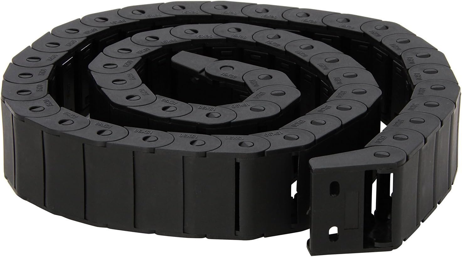
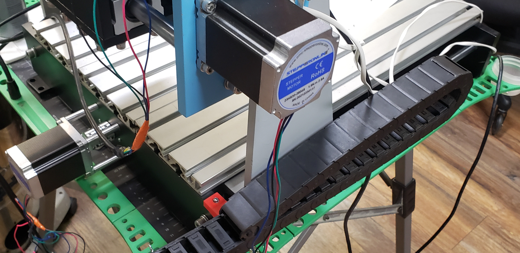
I used the same flexible cable chains as for my 3D printer. The printer has even more wires, but everything fit perfectly in those chains. These chains didn’t disappoint this time, either.
In the past, I tried many different chains from various manufacturers. Of course, I’m talking about the lower price range. Most chains in this category suffer from poor flexibility, bending in unintended directions, breaking at joints, and so on. After plenty of trials and countless returns, I finally found some genuinely decent ones.
As usual, I followed the concept of “cable autonomy.” This concept has proven itself 100% in previous projects! The idea is that no wire runs continuously from the power source to the consumer. Instead, it’s broken into segments linked to specific flexible chains and machine modules. Wires are connected between chains using connectors, forming necessary branches. This can be visualized like so:
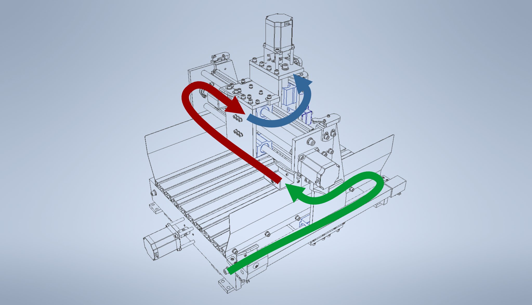
In the schematic (loosely defined):
- Green: The Y-axis branch and everything associated with it.
- Red: The X-axis branch and its components.
- Blue: The Z-axis branch and its elements.
Advantages of this approach:
- Simplified Upgrades and Repairs
If you need to upgrade or repair the system, you don’t have to replace an entire wire from start to finish. You only need to modify the relevant section of the branch. - Convenient Handling
You don’t have to work on the system while it’s installed on the machine, often in hard-to-reach places. You can disconnect a cable chain, take it to your workbench, and comfortably make the necessary changes. Then, simply return the chain to its place and reconnect the connectors. - Easier Mechanical Maintenance
For example, if you need to replace a bearing in the Z-axis carriage, which holds the spindle, limit switches, lighting, and who knows what else, it would be difficult to disconnect everything if the wiring runs directly to the control unit. The carriage would remain “tied” to the machine by its wires, forcing you to work on it in an awkward position. With autonomous cable chains, you can easily detach the carriage, bring it to the workbench, and work on it comfortably. Afterward, just reinstall it and reconnect the wiring. - Improved Transportability
The machine is effectively composed of conditionally independent blocks. These can be quickly disconnected and then just as easily reassembled in a new location. Dividing the machine into four independent parts — the table, Y-axis, X-axis, and Z-axis — makes it much more transportable and compact. Not that I’ve ever needed this for my machines, but you never know…
Disadvantages:
- Requires Careful Organization
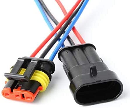
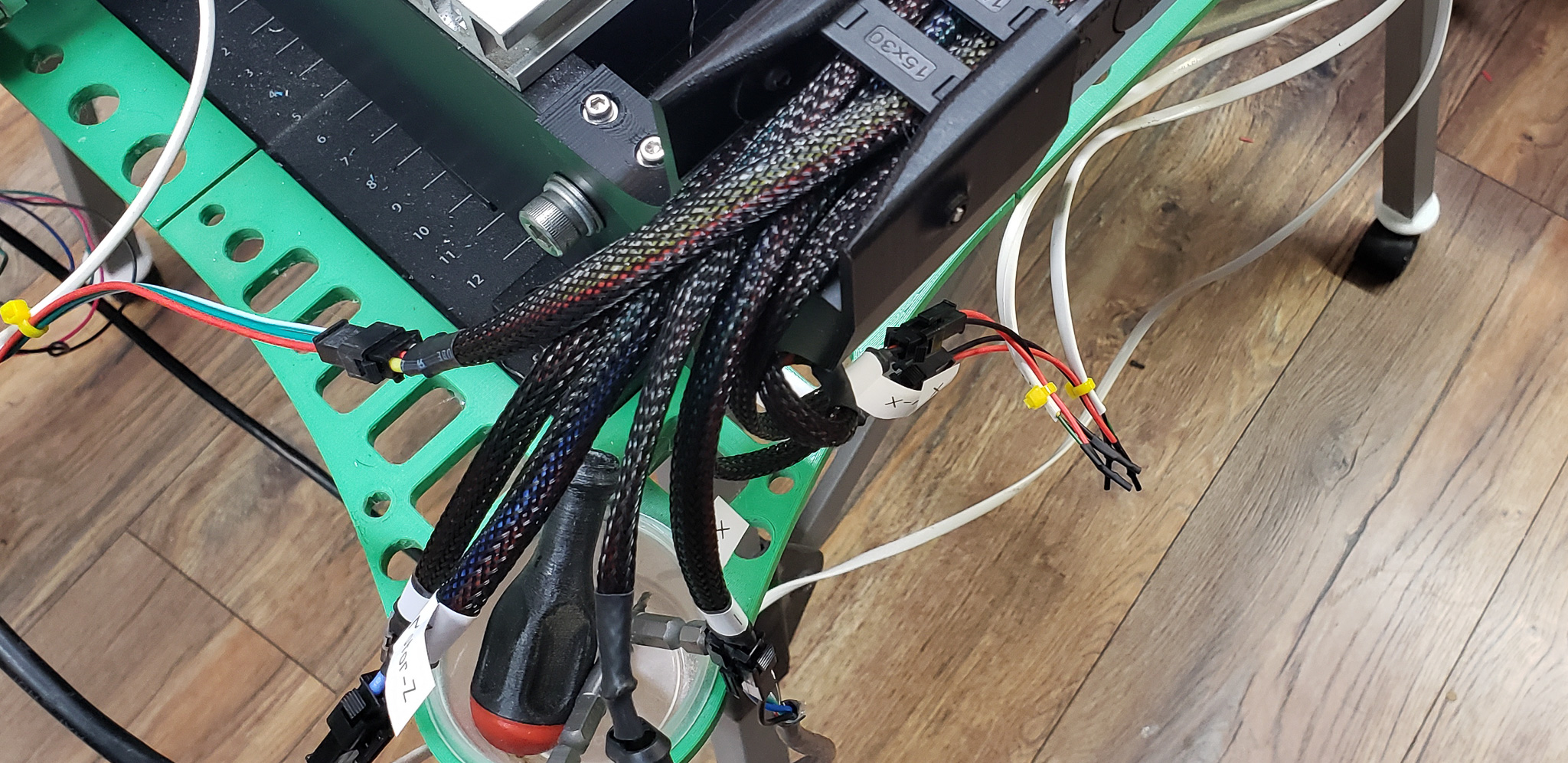
The connection points of branches and their connectors must be localized and grouped. Otherwise, the resulting tangle of wires can become confusing, negating the benefits of this modular approach. - Lots of Connectors
For example, the longest branch — the spindle power supply — is broken into four segments. This means reliable locking connectors are necessary. For signal and low-voltage branches, I used JST SM connectors. For the high-voltage spindle branch, I used automotive connectors (not sure of the exact type):
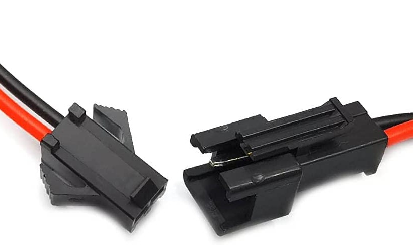
While connectors do introduce “weak points” into the system and make it more complex, the benefits still outweigh the drawbacks. I’ve seen this proven many times.
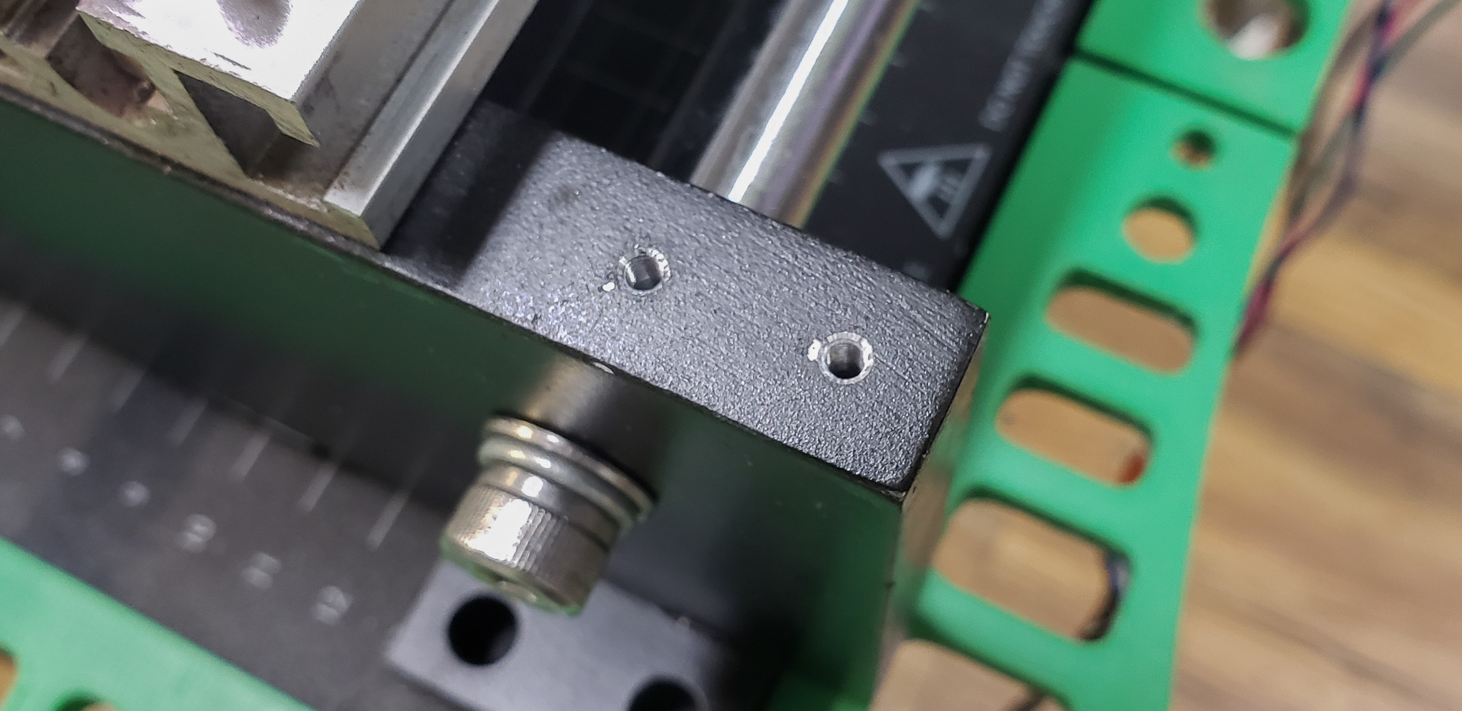
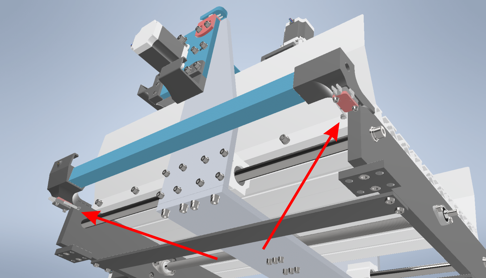
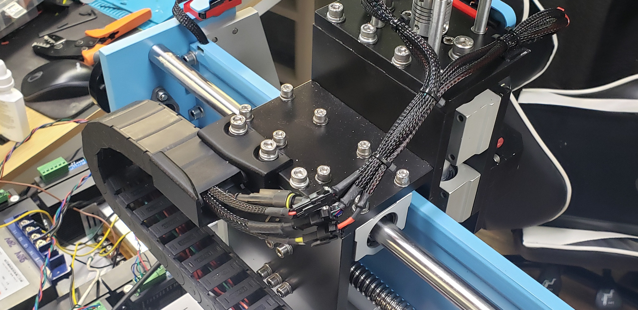
For mounting the chains, I had to design custom brackets. Typically, the first and last links of a cable chain have mounting holes, but in this case, they were useless because the machine’s structure wasn’t designed for them. I had to invent my own brackets (e.g., for the X-axis chain):

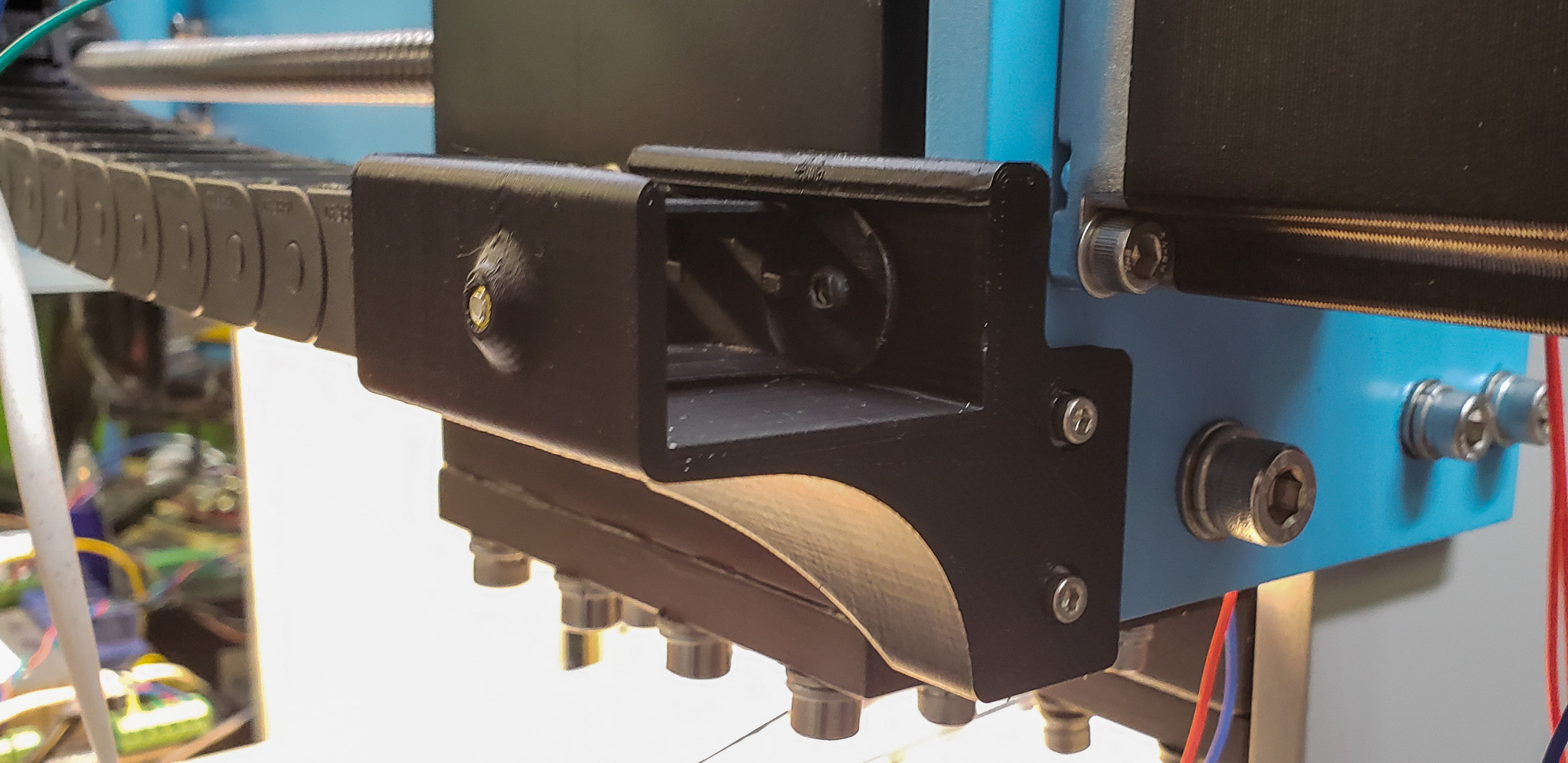
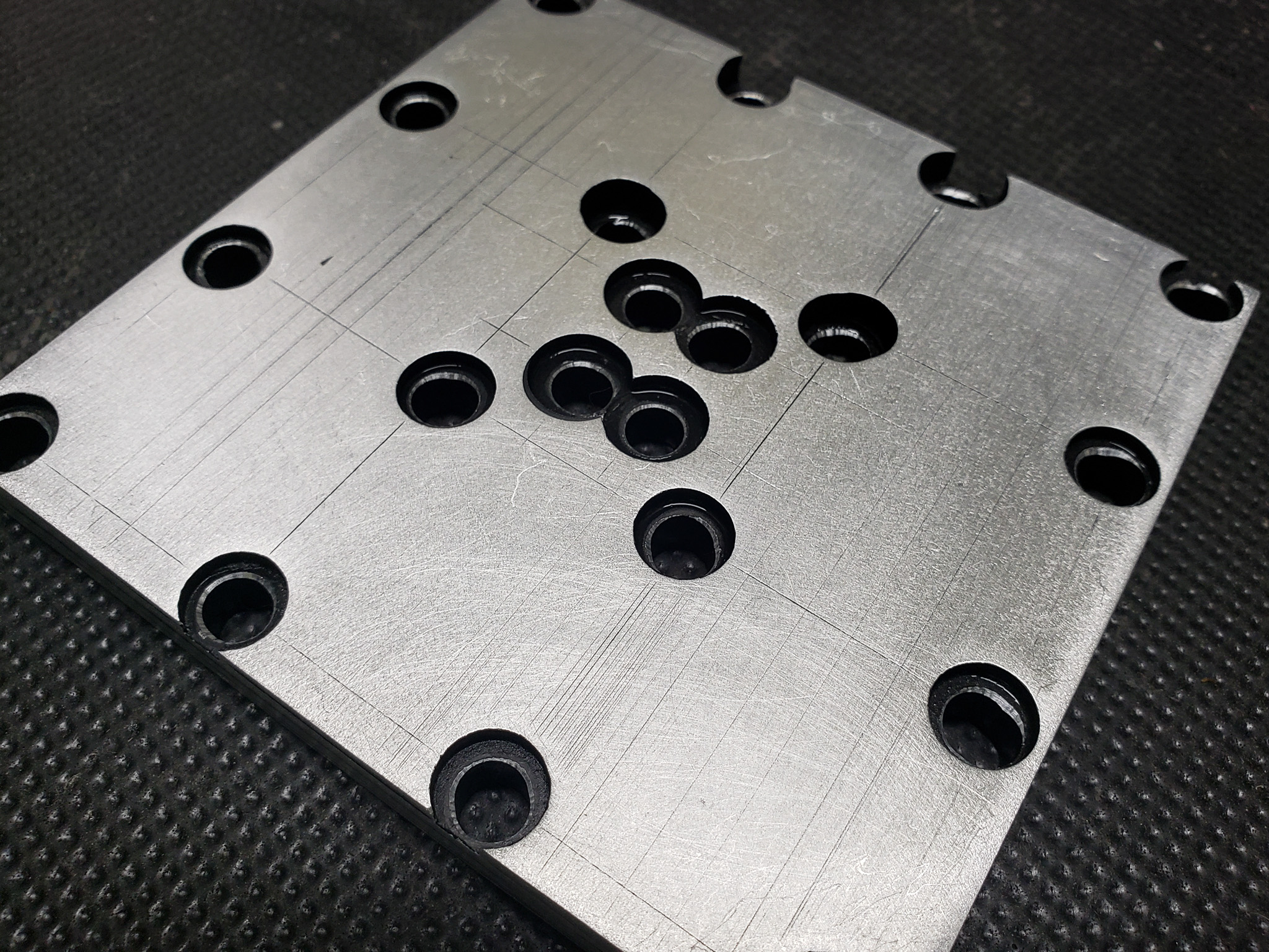
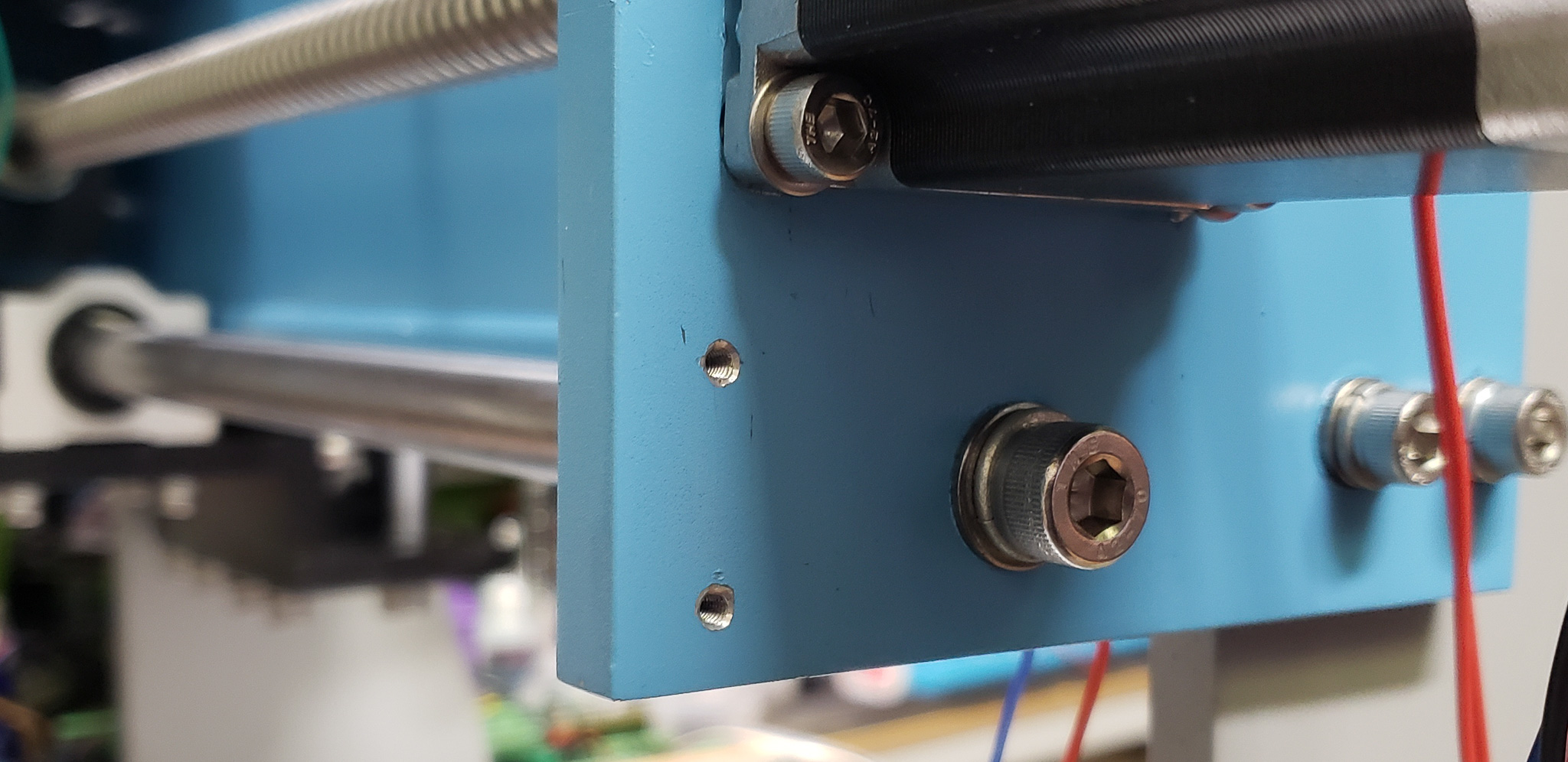
In places where these brackets couldn’t be attached to the machine using existing bolts, I had to drill additional threaded holes:
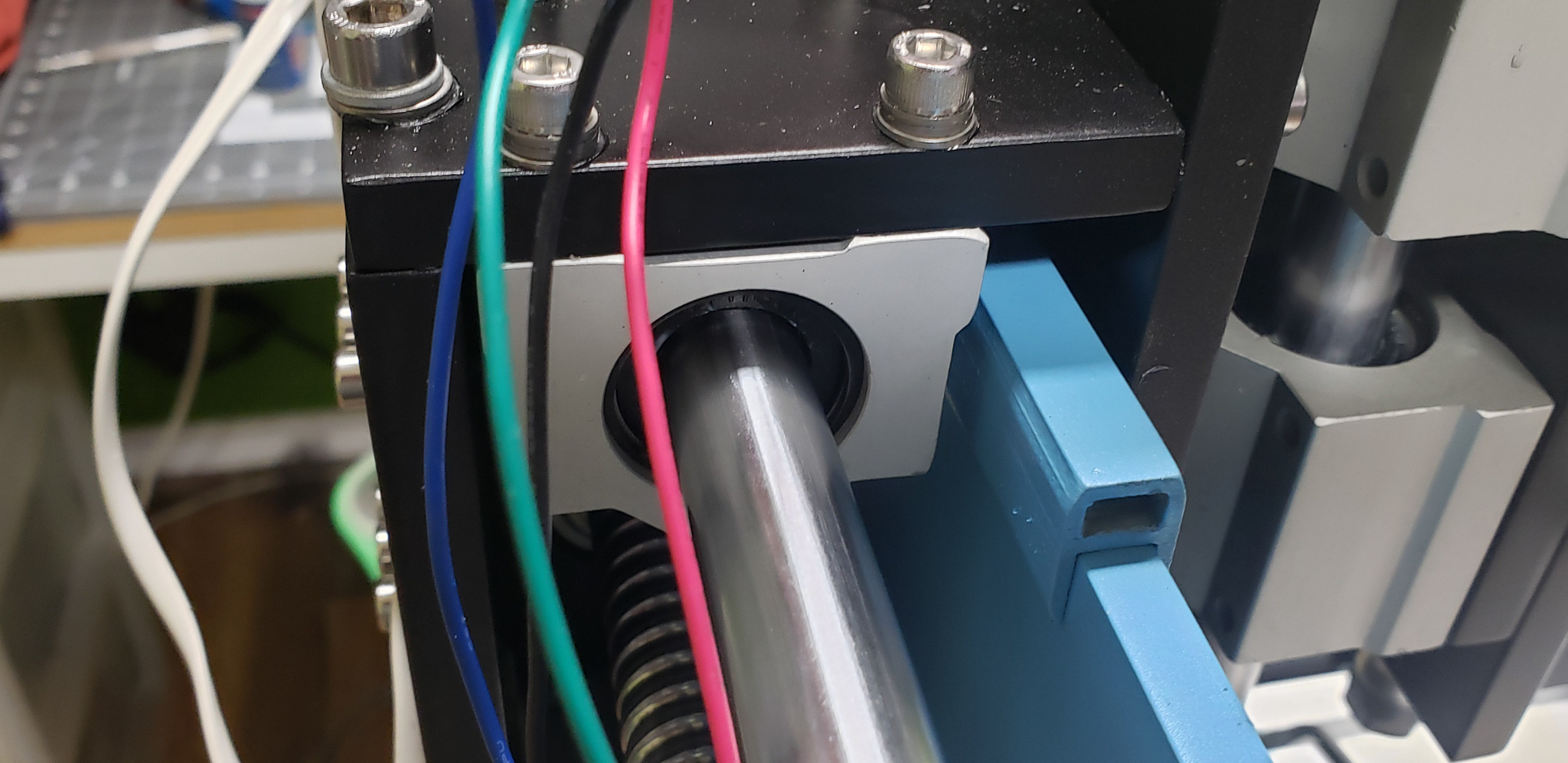
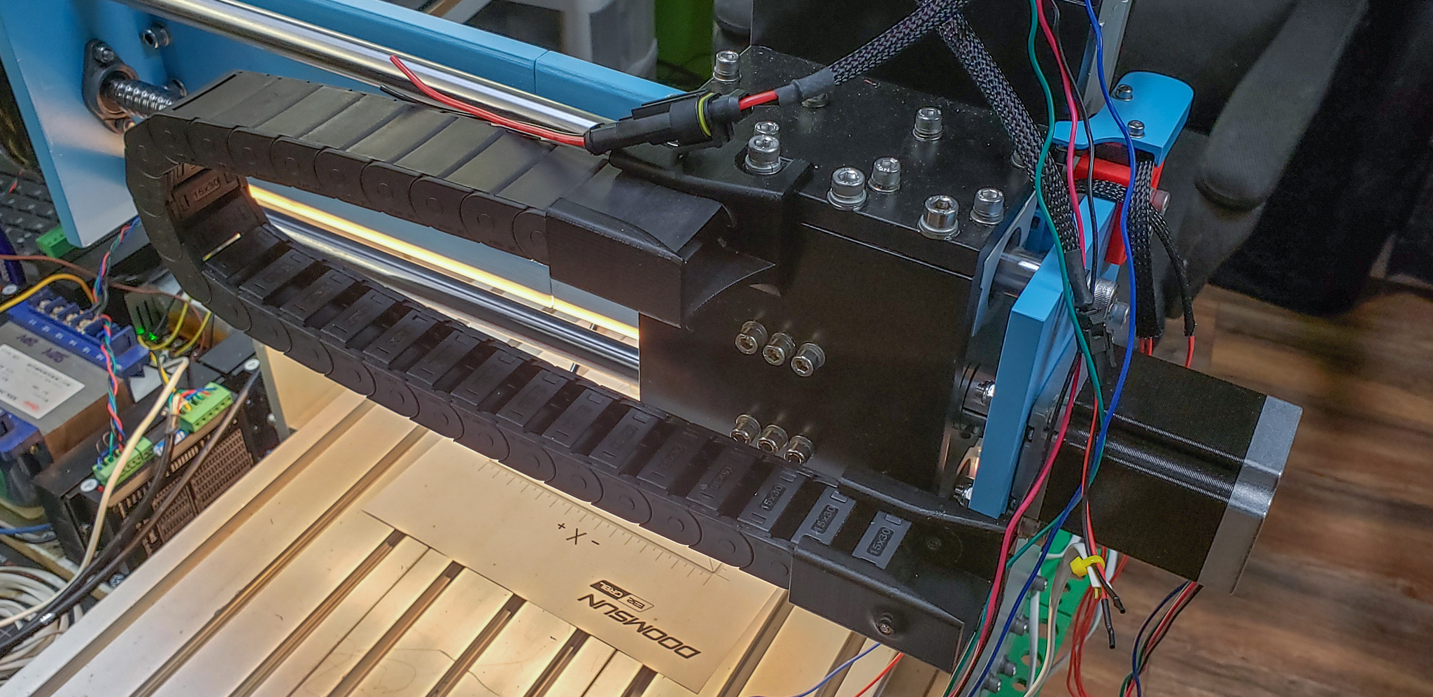
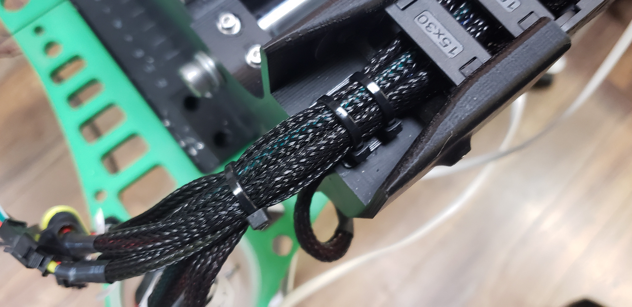
Furthermore, I added an aluminum square-section tube, which I’ll refer to as the “beam”:
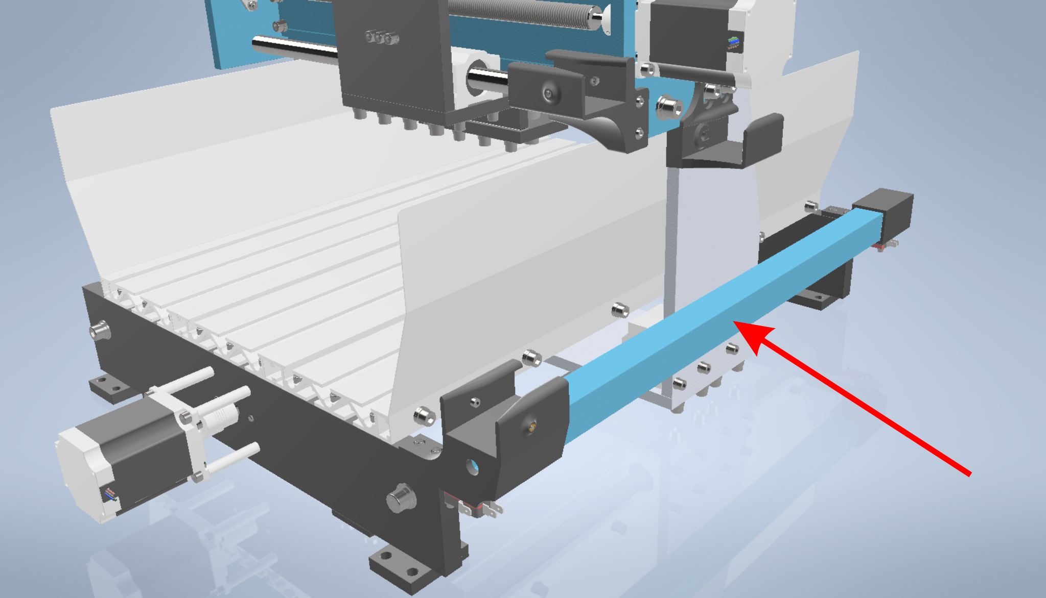
This beam supports one of the cable chains. It’s fairly long and holds many wires. In fact, it carries all the machine’s wires, as it’s the first in the chain. This makes the chain relatively heavy and prone to sagging. While not critical, it looks unattractive. The beam prevents this:
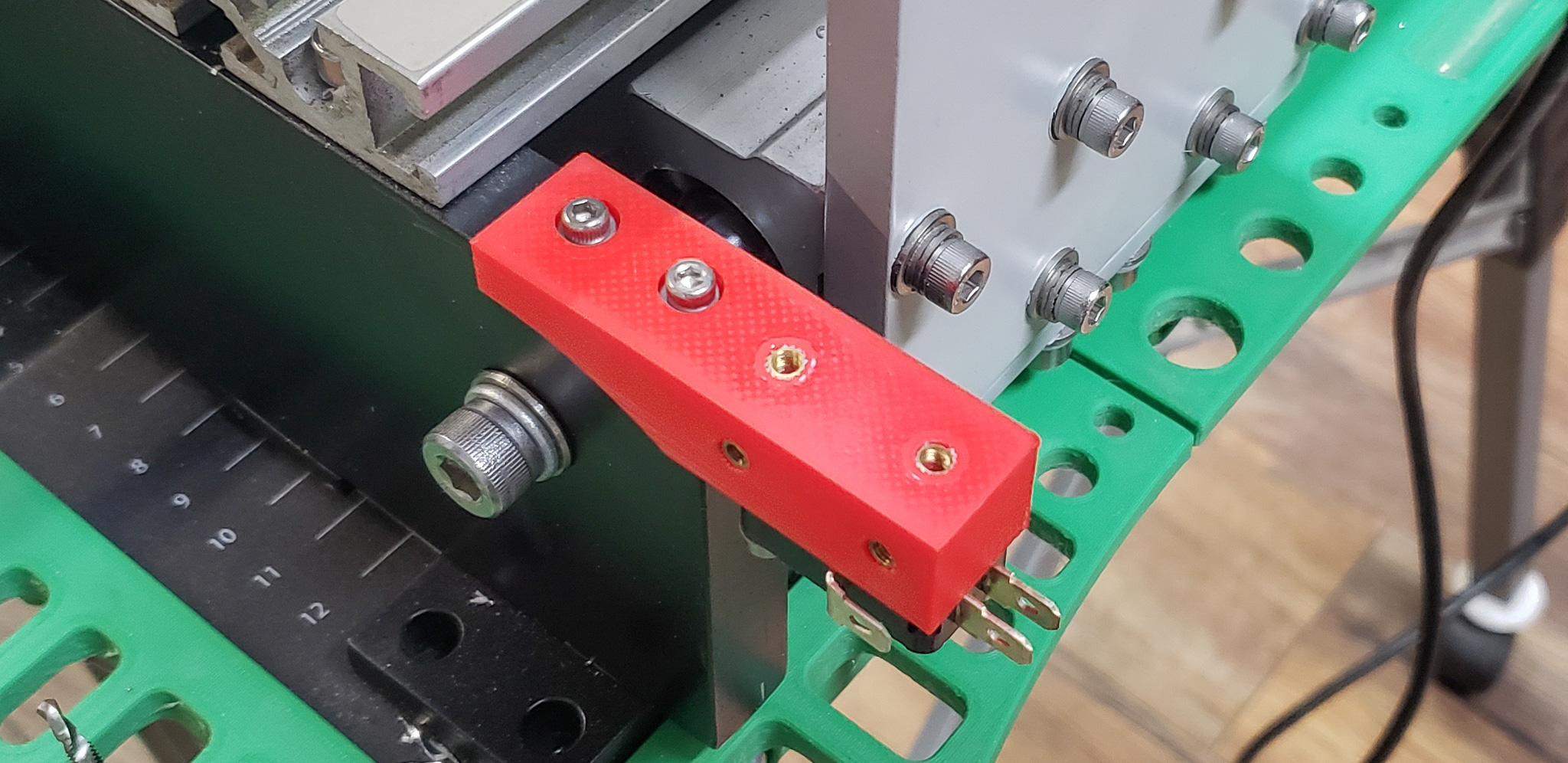
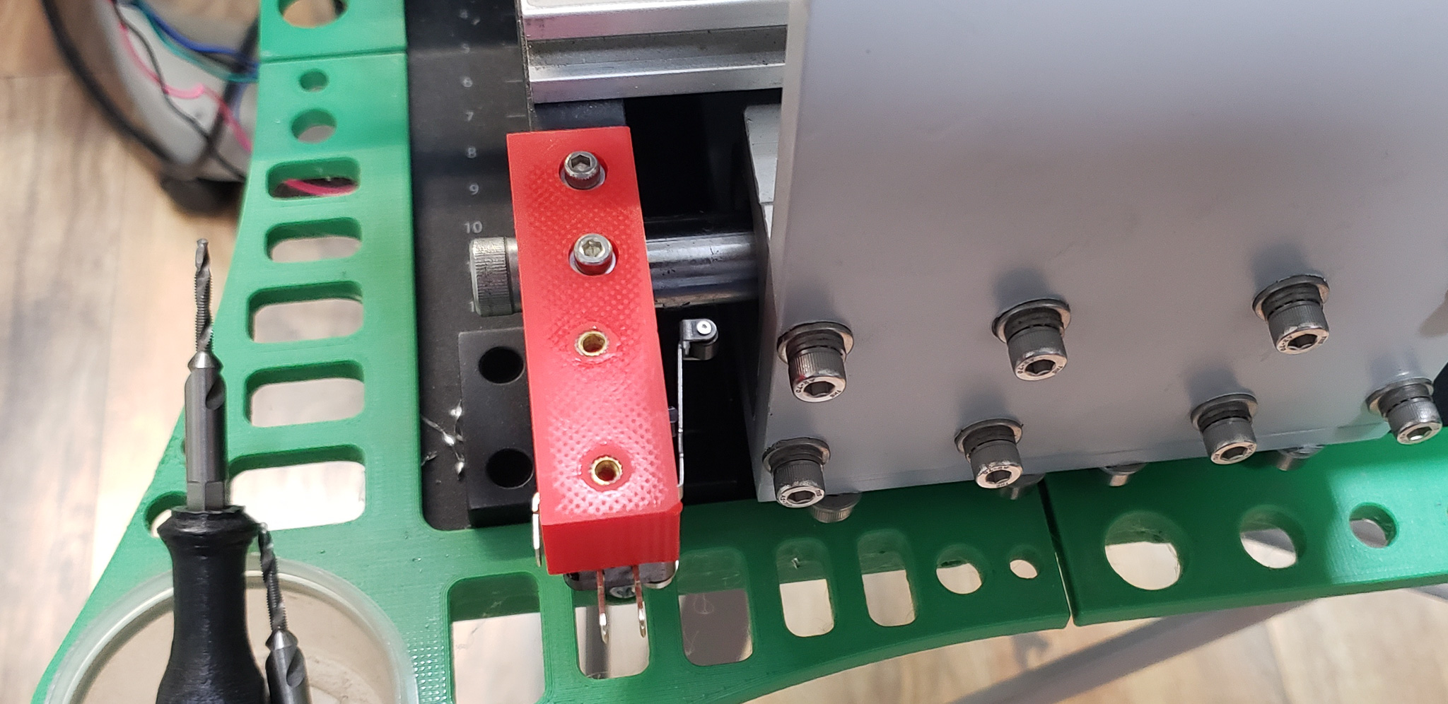
Additionally, the beam’s brackets also serve as mounts for the Y-axis limit switches. You can’t see it in the photo, but they’re tucked away underneath all this:
Naturally, the wires that don’t go into the chain are routed through this beam. This is a small independent group, consisting of wires for the front limit switch and, in the future, a front-mounted connector for a detachable probe.
In the future, the beam might also carry a wire for a manual control console, and the beam itself could serve as the console’s mounting base. I’m still undecided about whether such a console is necessary. On “professional” machines, it’s usually a folding “ear” attached to the side (sometimes even detachable, if small and without a screen):
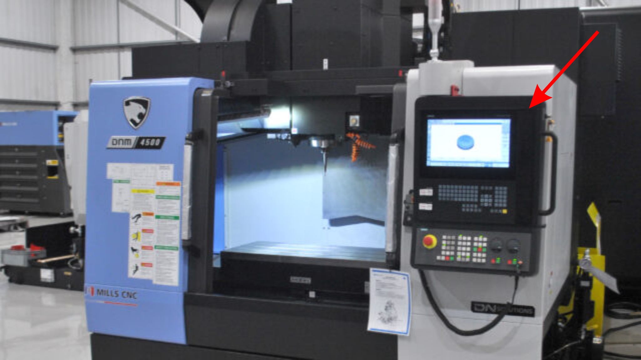
I’m skeptical that such a console would make sense in this case, but… time will tell.
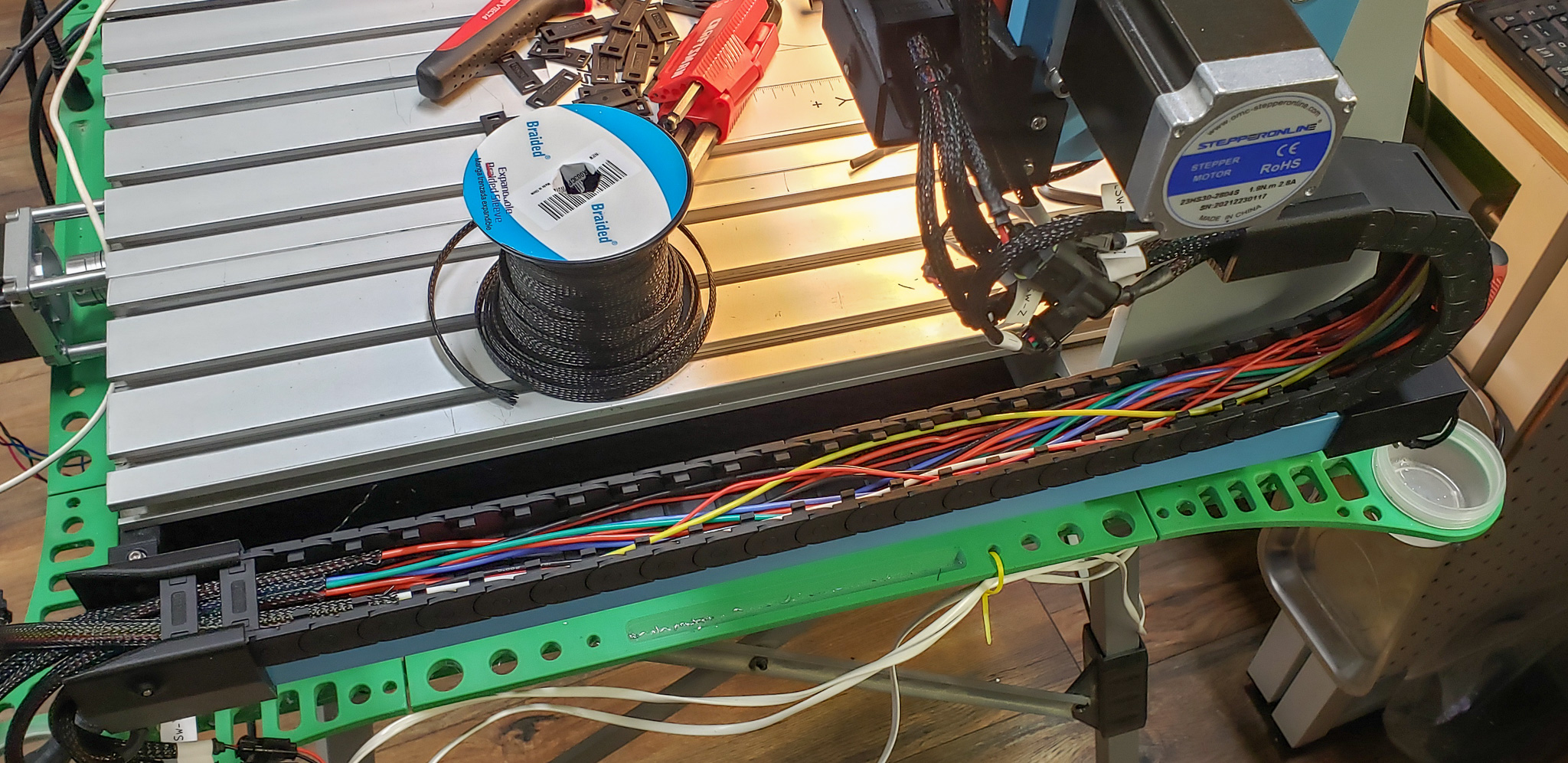
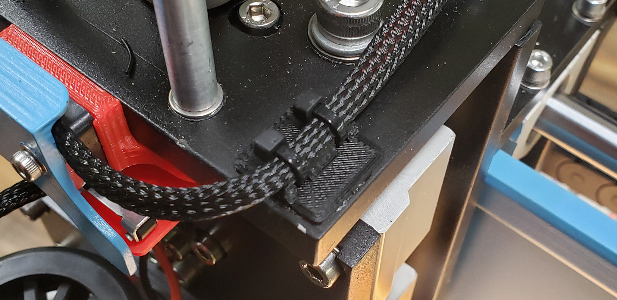
Back to the wires… Outside the chains and the beam, all wires are encased in nylon sleeves. Loops are secured with specially printed “pads” featuring eyelets for zip ties. Connectors are grouped into clusters and labeled:


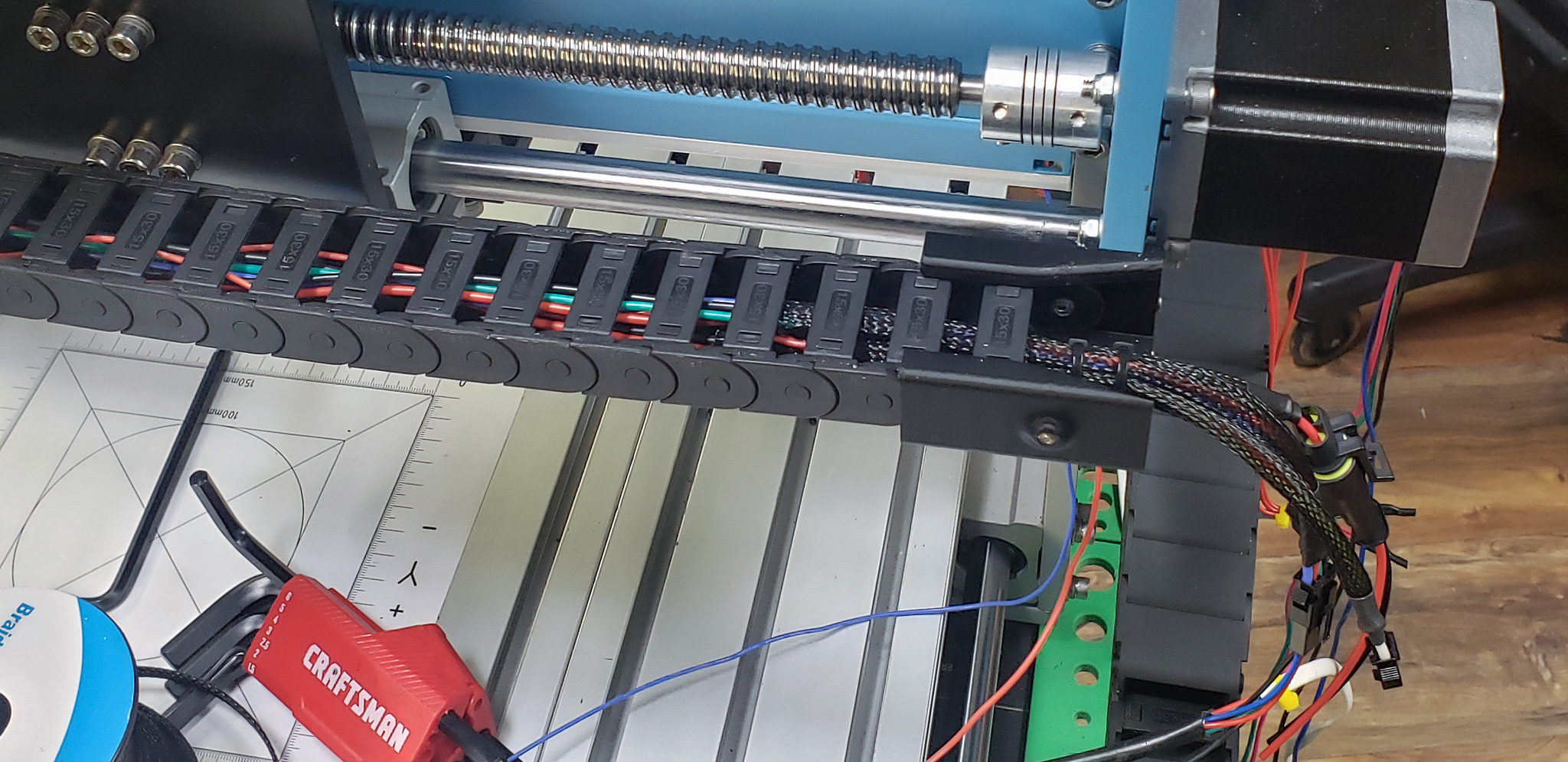
The wires themselves vary depending on their purpose:
- 16GA for the spindle,
- 18GA for the motors,
- 22GA for low-voltage electronics.
All are silicone-based, flexible, and consist of many fine strands, almost hair-like. They are highly resistant to repeated bending within cable chains.
In the 3D printer, this was once a serious problem. Standard wires frequently broke inside the chains. Since switching exclusively to these silicone-based flexible wires, I’ve had no breaks in several years. I’ve become a big fan of this wiring type, especially since it’s now widely available (though more expensive than standard wiring).
One last note on the wiring… Despite their many advantages, the flexible chains used in this project have an inherent flaw. In certain conditions, metal shavings can get inside and grind or damage the wires. Even chains with fully closed segments aren’t immune — shavings can still slip between the joints. I’m aware of this issue; it’s not new. On “professional” machines, the solution is straightforward: cover the chain with a fabric sleeve, typically made of canvas or rubberized cloth. In this case, any tightly woven fabric would suffice. For now, I’ve decided not to cover the chains and will observe how critical this issue becomes over time.
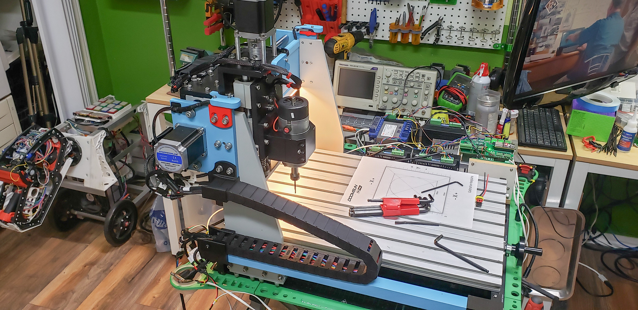
Even before completing the beautiful wiring described above, I had the urge to see the mechanics in action — to get a firsthand look at what all the suffering was for.
By that point, a friend had already provided me with a board for the controller and all the necessary modules. He did a stellar job — much gratitude to him. He even soldered the connectors to the board, leaving me with just the task of hooking up the wires. To top it off, the motor drivers had arrived by then as well. Essentially, there was nothing stopping me from getting the few assembled components moving.
Thus, the Temporary Control Unit (TCU) was born. And it was horrifying! A true masterpiece in the spirit of plumbing hacks, DIY farm fixes, and Indian tech YouTube videos! Everything was held together with tape and wire nuts, with almost every possible rule of electrical safety blatantly ignored — exposed contacts, dangling wires, open components, and so on.

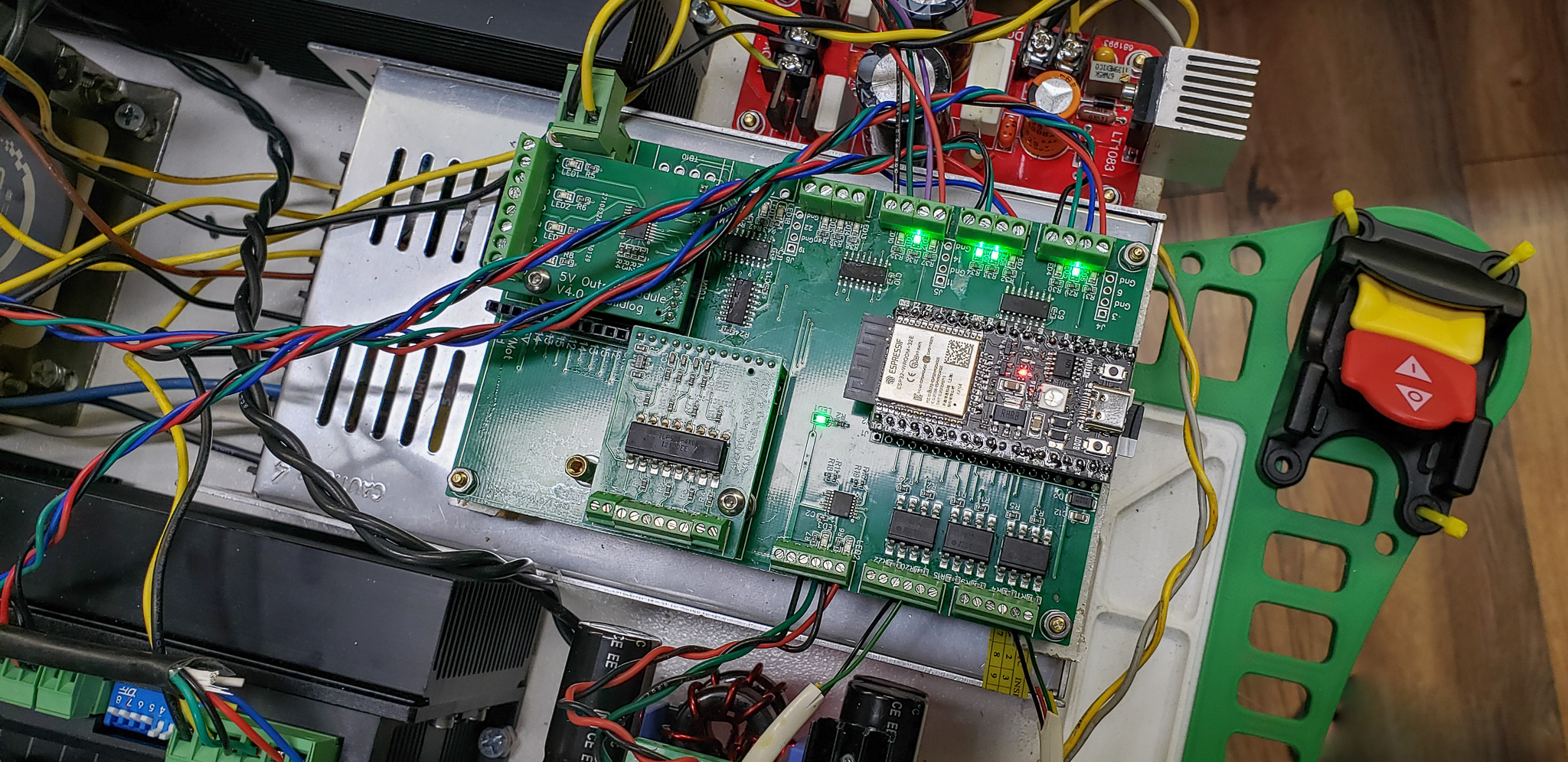
The sole purpose of this marvel was to survive for a week or two, hopefully without electrocuting anyone permanently. Long enough to test the basic interactions between the mechanical and electronic components. Its lineup included:
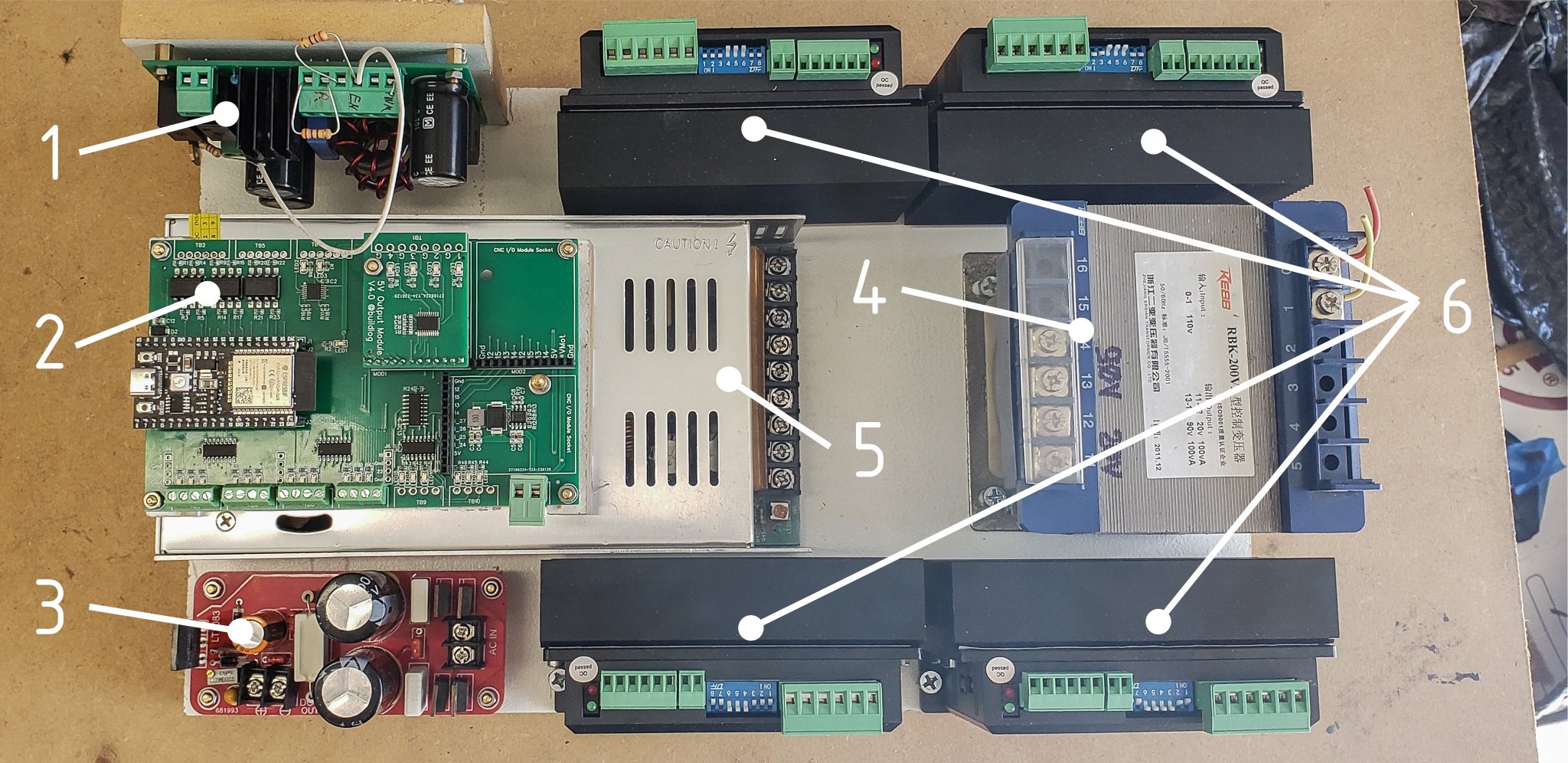
- A module to control the original spindle.
- The controller board, its controller, and modules.
- A rectifier with a transformer.
- The transformer itself.
- A power supply unit (24V, 600W “brick”) for the motors and controller.
- Motor drivers for the X, Y, Z, and A axes.
The transformer and rectifier (points 3 and 4) were purely temporary solutions, as was the spindle controller (point 1). The new spindle arrived much later, well after the mechanical part of the project was completed. Until then, the machine used the old motors and the old spindle. The old spindle required 110V DC (yes, DC!) to operate, hence the need for the transformer and rectifier. Everything else was powered by the 24V brick mentioned in point 5.
The machine’s first deliberate movements were “homing” for the Z and X axes:
Shortly after, one of the original motors died. It suddenly started overheating, and the intelligent driver immediately triggered a fault shutdown. The magical smoke didn’t escape from the motor, but it refused to work anymore. This didn’t cause much distress, as it served as a good test for handling unexpected situations. Besides, the motors were already slated for replacement with newer, more powerful ones, as mentioned earlier.
Finally, a “tray” was added to the machine’s design.
Anyone who has even briefly interacted with similar machines (of any size or class) knows that their primary job is to produce chips. They produce an incredible amount of them! Even if the machine is fully enclosed with an automatic chip removal system, chips will still end up everywhere. This is inevitable, and you just have to accept it. The sky is blue, grass is green, humans have two sexes, the Earth is round, and CNC mills produce chips. This is how it was, is, and always will be, regardless of what anyone might think.
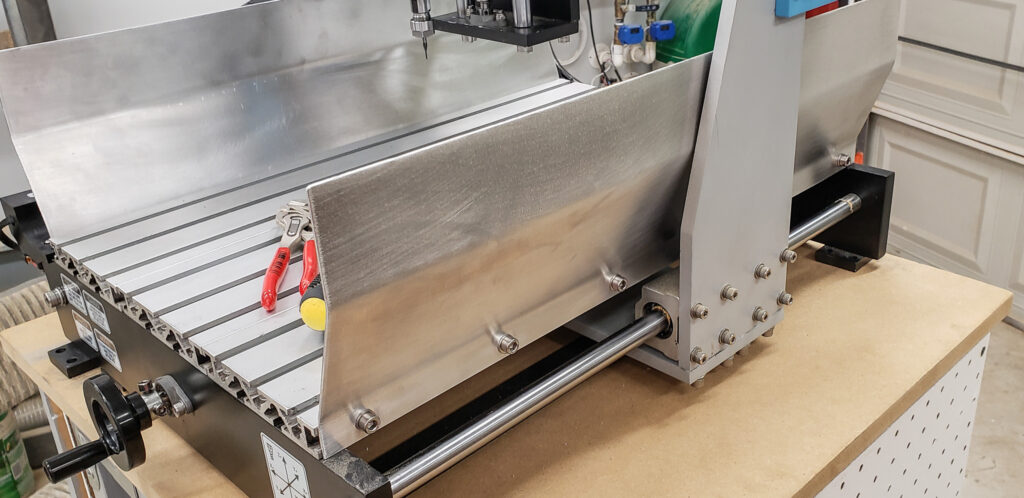
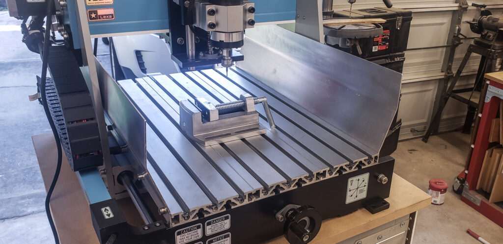
To protect the sensitive components of the machine and save myself a lot of trouble, I decided to shield the working area with improvised deflectors:

These don’t eliminate the need to wear safety glasses during operation or spend an hour sweeping up afterward. However, they make the spread of chips more predictable: most of the chips stay within the working area on the table, some fly forward and backward, and just a few follow strange trajectories upward. What they definitely won’t do is fly toward the horizontal rails of the Y-axis, clogging the bearings.
For “woodworking” CNC routers, this problem is more or less successfully addressed with a powerful vacuum or dust collector, whose hose is positioned close to the cutting tool. However, with metal, this approach is less effective. Even without using cutting fluid, vacuums struggle to capture metal chips flying out from the tool. The weight of metal particles and the energy they retain during cutting are significant. And with cutting fluid in play, even powerful “garage-grade” vacuums and most stationary dust collectors are utterly useless.
This led me to dig out a tool I’ve only used once in my life and whose purchase I’ve often regretted… A bender (not the robot from Futurama)! Big, heavy, always in the way, and generally useless for my projects — except for one instance many years ago when I needed to bend a wide strip of sheet metal. Finally, its moment of glory had arrived:
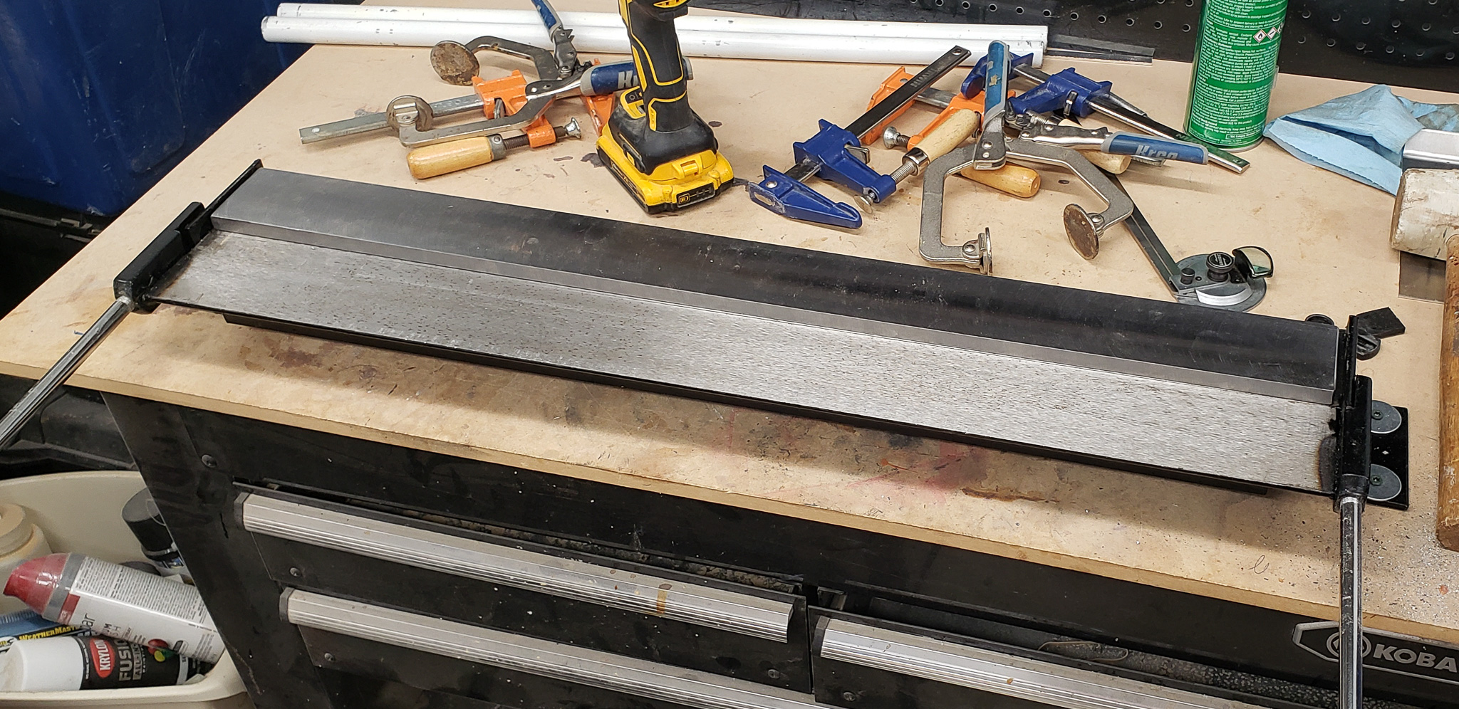
For the deflectors, I used 2 mm thick aluminum sheets. This thickness was literally at the limit of the bender’s capabilities. I’d even say it exceeded them — bending a small test piece of aluminum by hand took all my strength:

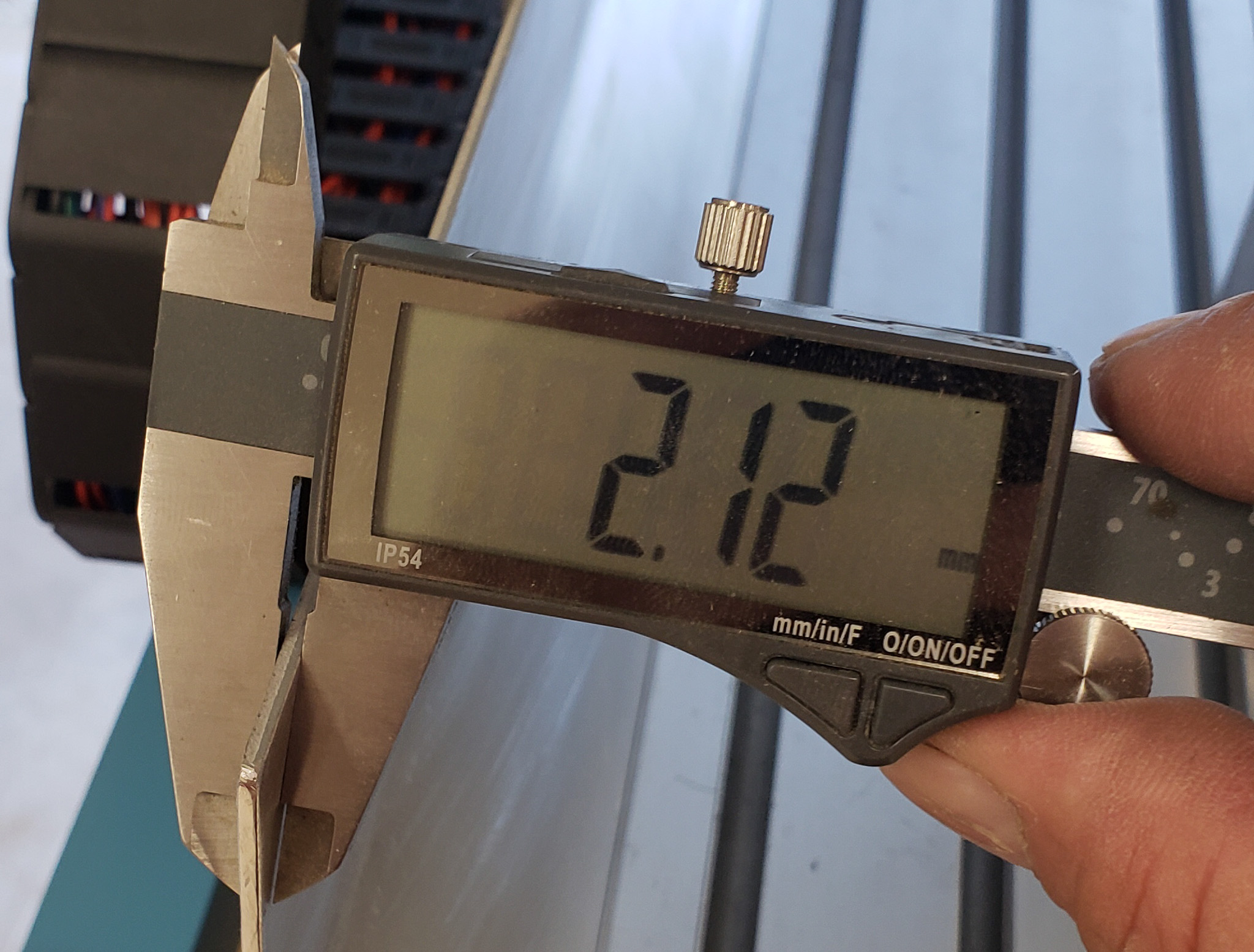

To bend the deflectors for the entire tray, I had to extend the bender’s handles with sections of water pipes nearly five feet long to increase the lever arm.
But the result was worth the effort:
All that remained was to hope the deflectors would perform as intended.
A note from the future:
They do! Oh, they absolutely do! The deflectors turned out to be an exceptionally effective and simple solution to the problem of flying chips.
The last thing the machine is missing is a proper control unit. Its creation will be the focus of the next article.
That’s all for now… To be continued here.