
The usual logical order for the brain is the X-Y-Z sequence. However, when building this type of printer, it’s more practical to follow a Y-Z-X sequence.
This is because it’s always easier to start construction from the base. In this type of printer, the base is the Y-axis. Once the Y-axis is in place, the vertical Z-axis can be mounted on it, and only then, as the final step, the X-axis can be added. Therefore, the sequence of posts in this series will reflect this order:
Y-axis.
It All Began with This Specific Y-Axis Component:
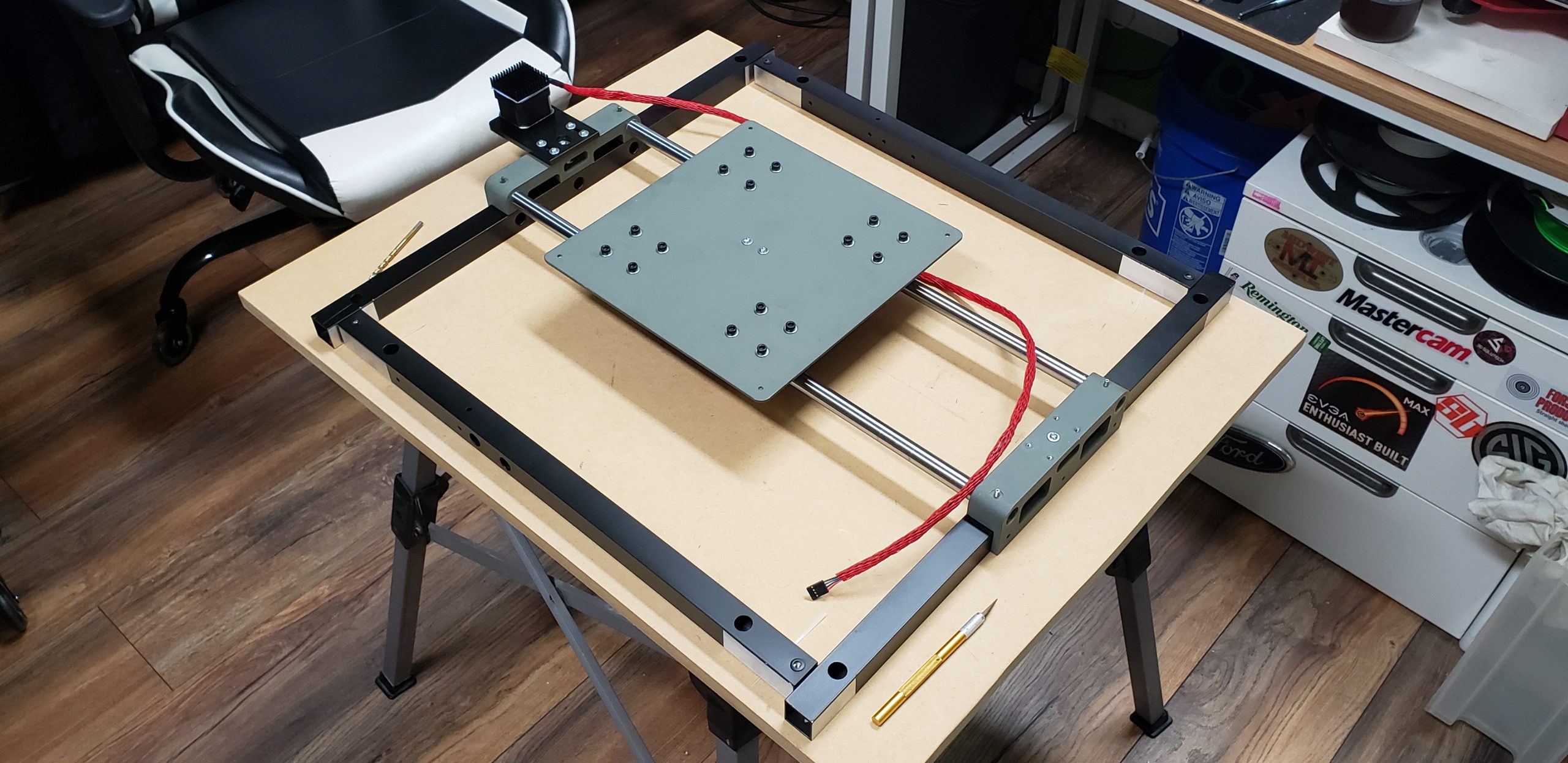
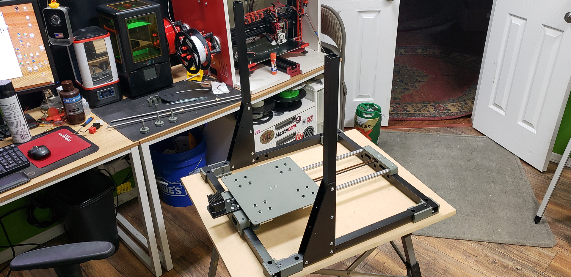
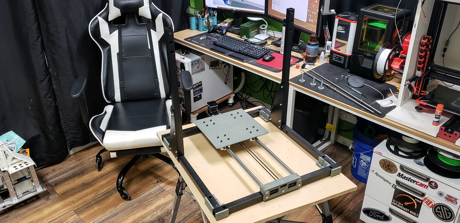
This part includes 16mm guide rails with CS16UU bearings, frame mounts, a heated bed, and a motor with a pulley that moves the bed along the rails.
The bed itself isn’t just a board on wheels. It’s a kind of “layered” structure consisting of a base plate that holds the bearings and the bed itself, mounted onto the base plate through corner springs. These springs allow for horizontal adjustment across all planes. This base plate under the bed was where the entire project started:
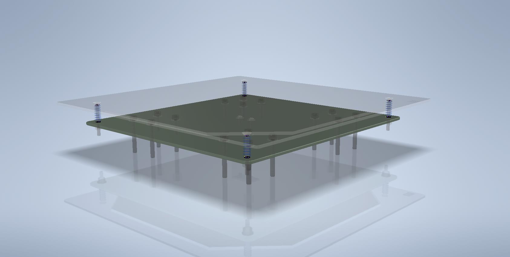
In my dreams, this was supposed to be a solid quarter-inch thick slab. Alas… Real life imposes quite a few restrictions on flights of fancy.
For instance, you could just go to the nearest hardware store and grab some aluminum… Sure, that’s an option… But what you’ll get is terrible quality aluminum. Thin-walled profiles and plates barely thicker than foil. And the cost of this flimsy junk? Comparable to an equivalent amount of adamantium! Finding a solid aluminum bar in an ordinary store? Practically impossible.
Thankfully, a friend directed me to a small shop in the neighboring town… “Shop” might be an overstatement. It felt more like a makeshift den in a shed for hardcore metal enthusiasts… But that doesn’t matter. What matters is that I found almost everything I needed there, and at very reasonable prices. Specifically, real 6061 aluminum with official factory stamps marked Made in U.S.A..
The only downside was their limited selection of sizes and shapes. For example, the only wide panel of a suitable size they had was just 1/8 inch thick. But hey, beggars can’t be choosers! Plus, they cut it to size for me right on the spot:
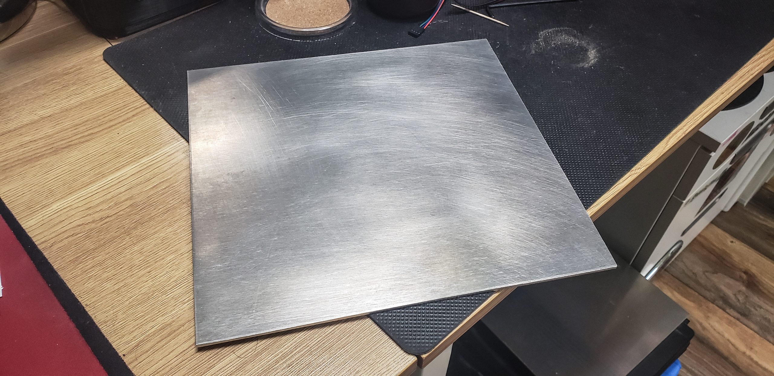
At the price they quoted me, I didn’t hesitate for a second and bought the entire sheet. Both the pieces they cut to size for specific parts and the leftover scraps. I’d have taken the shavings too if their cutting machine left any… This aluminum was just that good. After dealing with all the flimsy materials I’d been forced to use recently (like the frame for the mechanical dog), it felt like a breath of fresh air. It was satisfying to hold in my hands.
Of course, not everything could be cut precisely to size right there in the shop. Many parts had to be cut or finished at home. However, for the bed’s base plate, all that remained was drilling some holes.
For the first time in a long while, I ran into issues with measurement systems. Over the past decade, I’d thoroughly adapted to working with the imperial system. These millimeters? I can barely see them on a ruler anymore… Just a mess of tiny lines… And way too many of them!
Here, everything in the stores is sold in feet, inches, and their fractions. All the measuring tools default to those units. In fact, even the robots in our workshop calculate their movements using the imperial system, including the laser engravers. Even the ultra-modern Swiss machine from Mitsubishi operates in inches (well, thousandths of an inch). Everyone’s used to it, I’m used to it, and everything was fine…
An inch is simple, convenient, and intuitive. Unlike these millimeters tied to the wavelength of some unmentionable beam in a vacuum. I was perfectly happy — until this project with the damned printer came along!
So, all the raw materials, as I mentioned, were bought in inches. Most of the fasteners too. All my modeling software is set up to work in inches. But the electronic components I ordered from Amazon, Alibaba, and other platforms predominantly come in metric sizes. Or even better: for example, mounting holes in millimeters but overall dimensions in inches. A complete mess…
Honestly, I don’t care what numbers I type into the fields in my modeling software. It translates everything back and forth depending on the postfix I add after the number. Write “10 mm,” and the program will standardize everything into the units specified for the document. I can then feed this model to a robot, and it will sort everything out on its own, converting whatever units it receives into its motor steps.
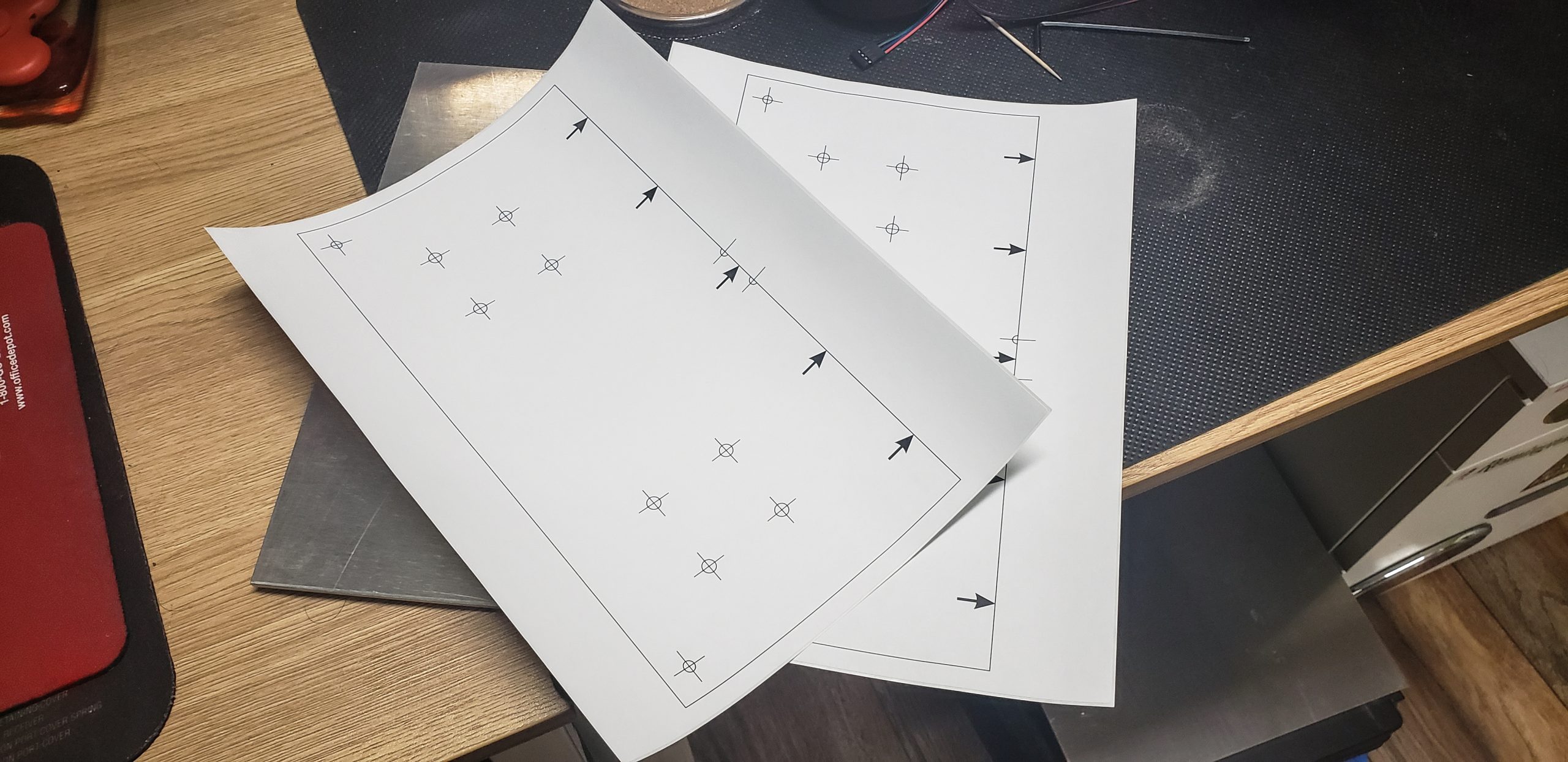
The problems begin when I have to mark something manually with calipers. For instance, a bunch of holes on this panel. The mounting holes for the heated bed are spaced in millimeters, while the ones for the bearings are in inches. Pretty quickly, I got tired of switching the calipers back and forth a million times or dealing with absurd fractions of millimeters or inches.
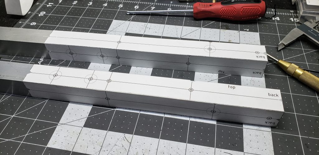
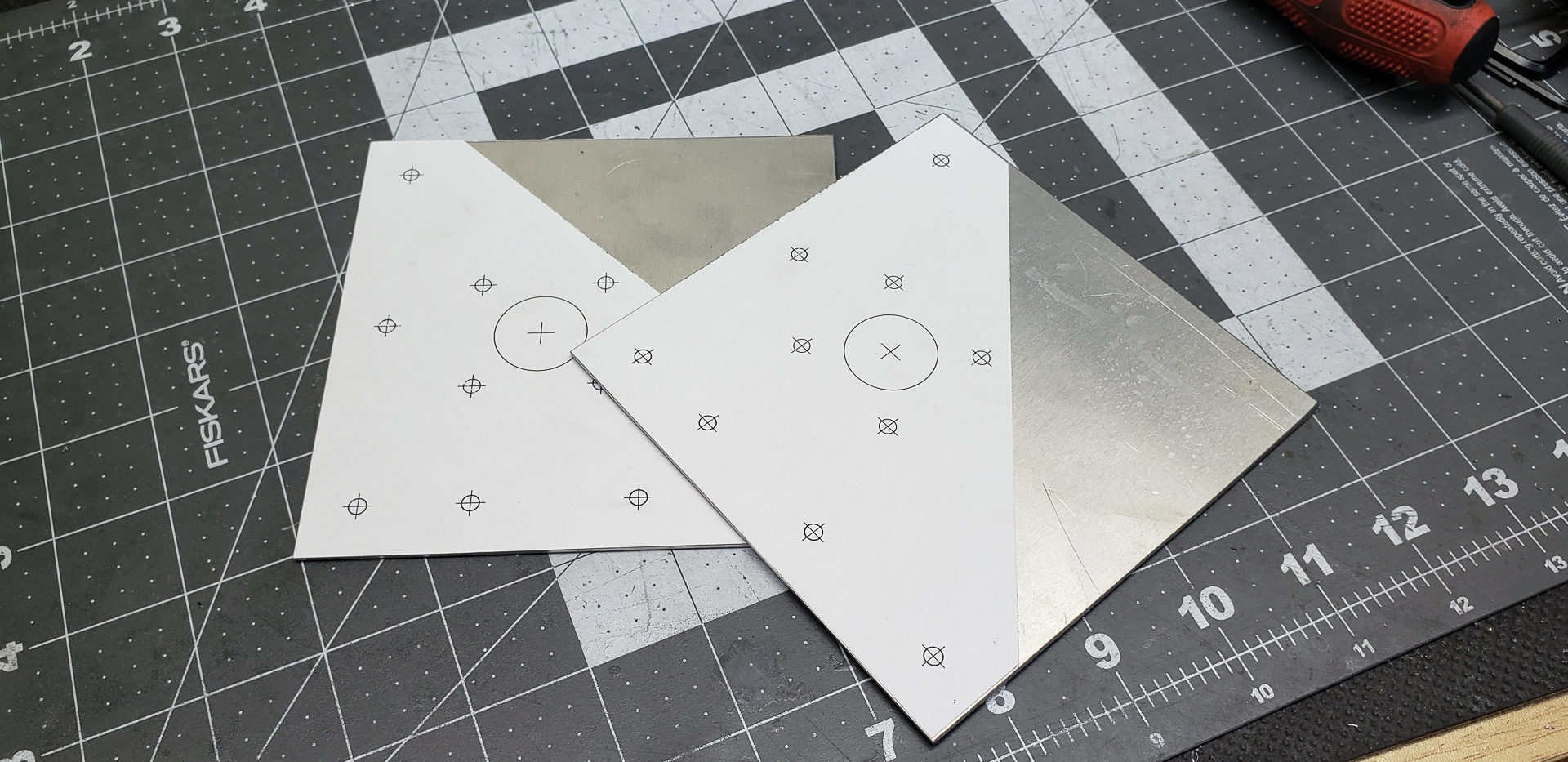
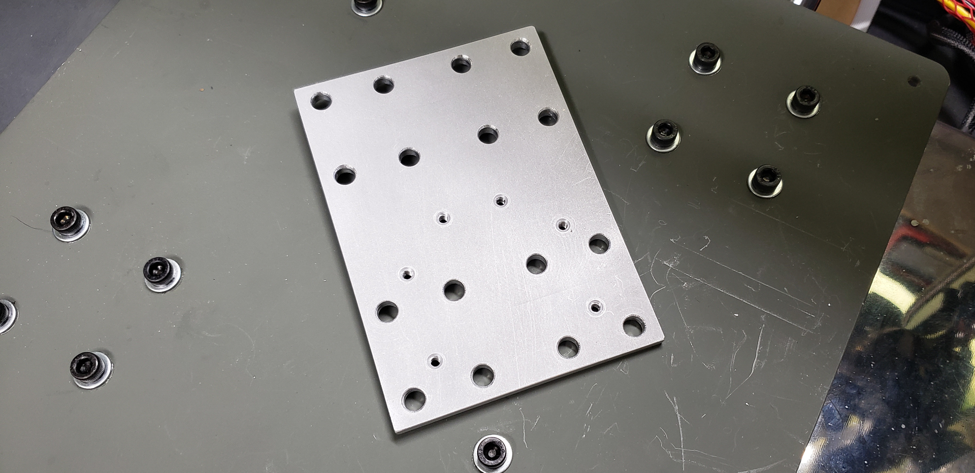
So, I simply printed out a template on adhesive paper, exporting it directly from the 1:1 model:
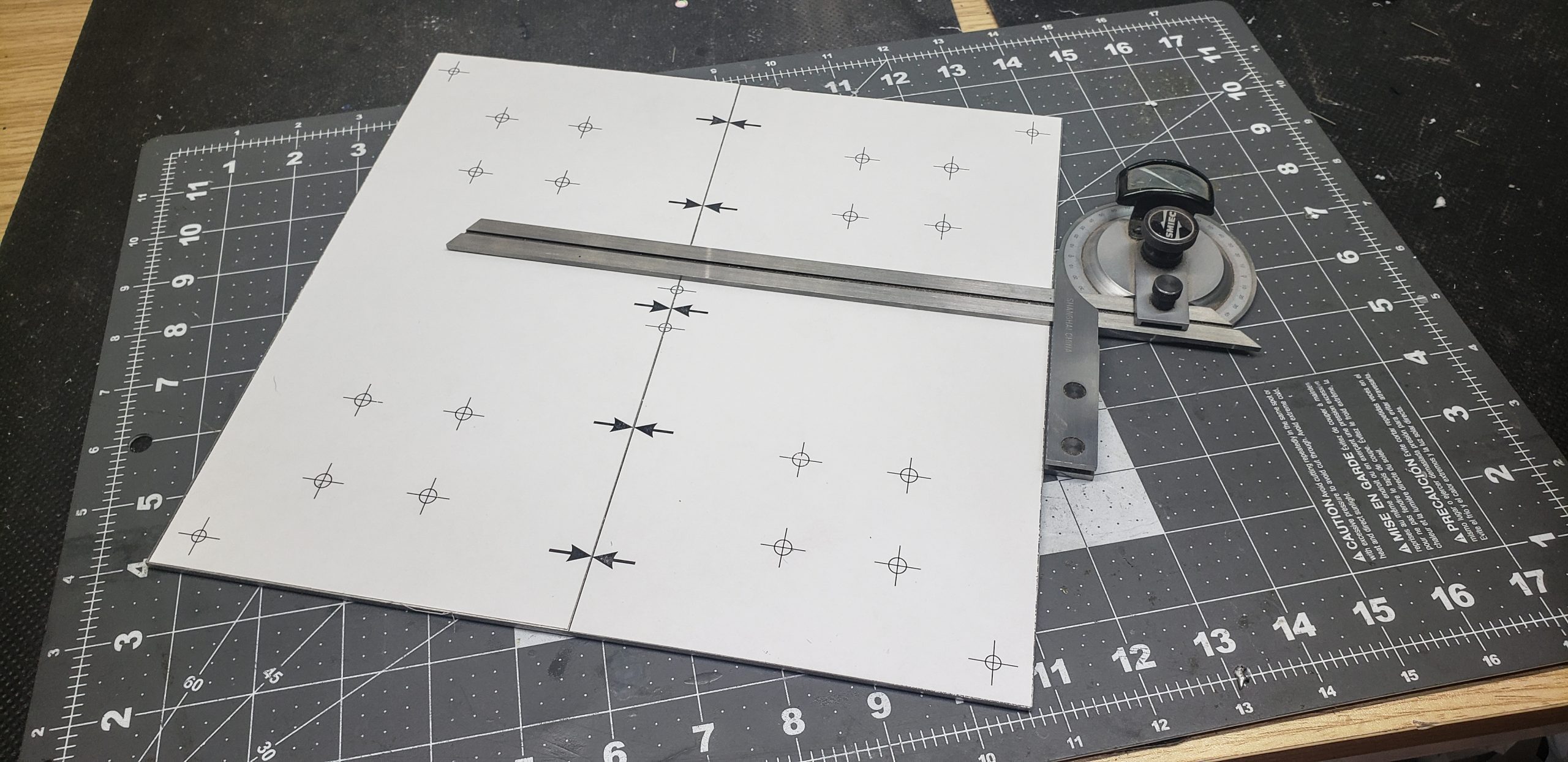
Using the template, I marked and drilled the holes:
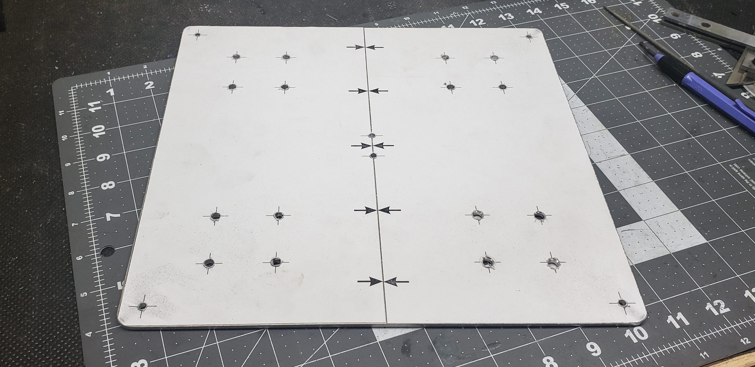
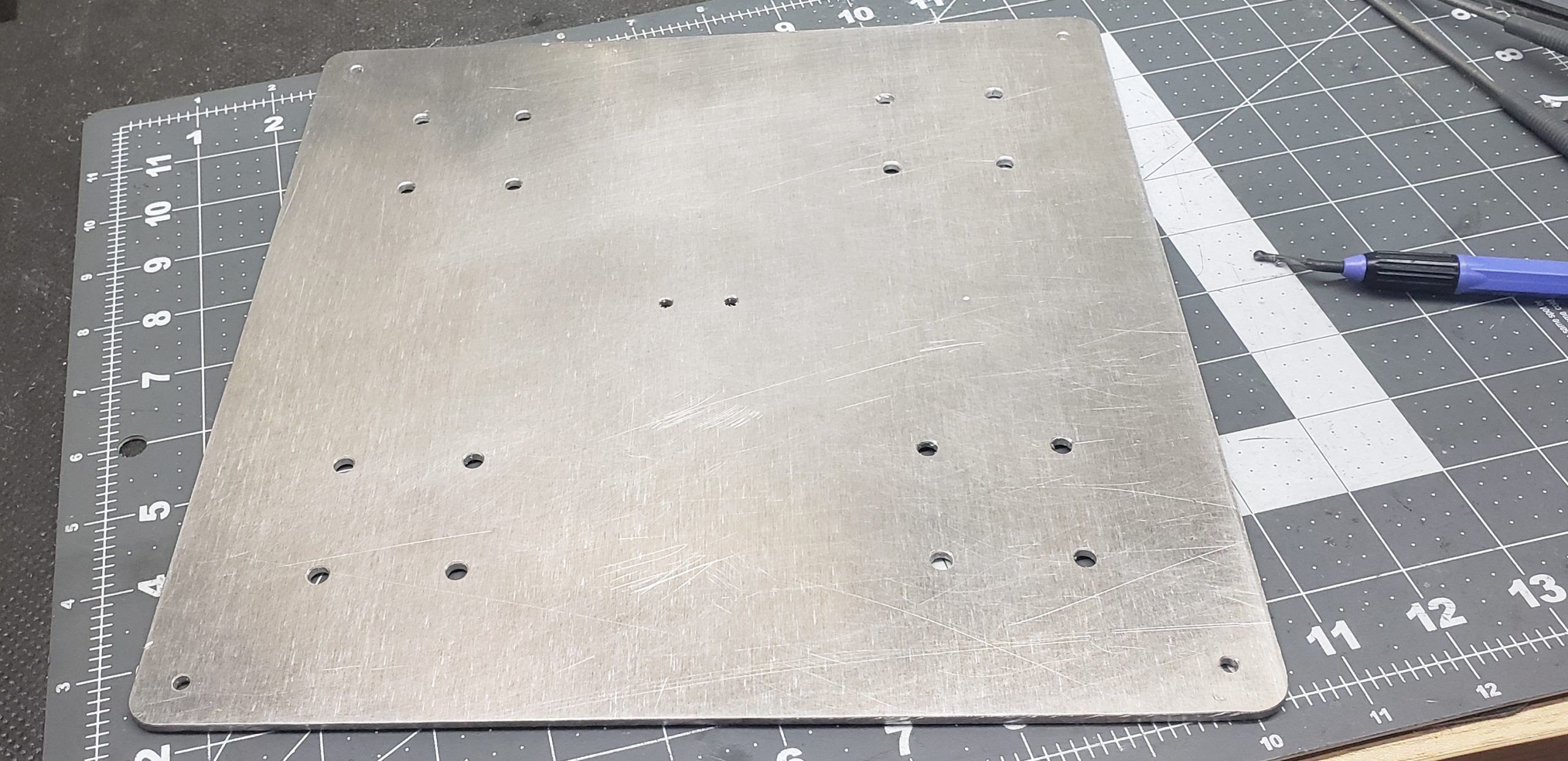
This turned out to be faster and more accurate than crawling all over the surface with a ruler, square, and calipers, transferring all those millimeters, inches, parrots, parsecs, and other astronomical units. Print, slap it on, punch, drill — and done. I stuck to this method for all other similar parts moving forward.
The first piece is done… Only a godzillion more to go…
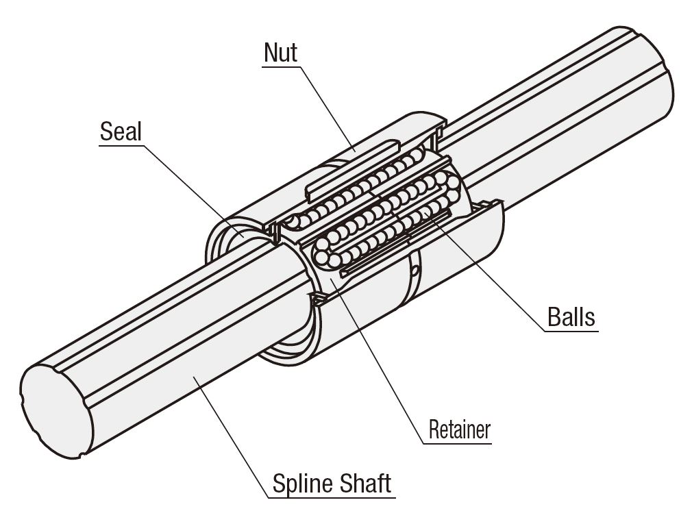
It was time to tackle the kinematics. And, as we all know, you can’t just go out, buy a couple of steel rods and a few bearing blocks, throw it all together, and expect a miracle. Unfortunately…
Every bearing needed to be disassembled, thoroughly cleaned of factory preservatives and metal shavings (!!!), packed with high-quality lithium grease, and reassembled — all while trying not to lose too many of the tiny balls in the process.
However, even this doesn’t guarantee the desired result…
Knowing what to expect, I bought two extra bearings for each axis. For the Y-axis, for instance, one bearing predictably ended up being scrapped — it jammed and crunched no matter what I did with it. On the bright side, it became a donor for a couple of missing balls in two other bearings.
Well, not exactly scrapped — it went into storage with a black mark labeled “Cruncher” on the side, just in case it could be useful for something less critical in the future.
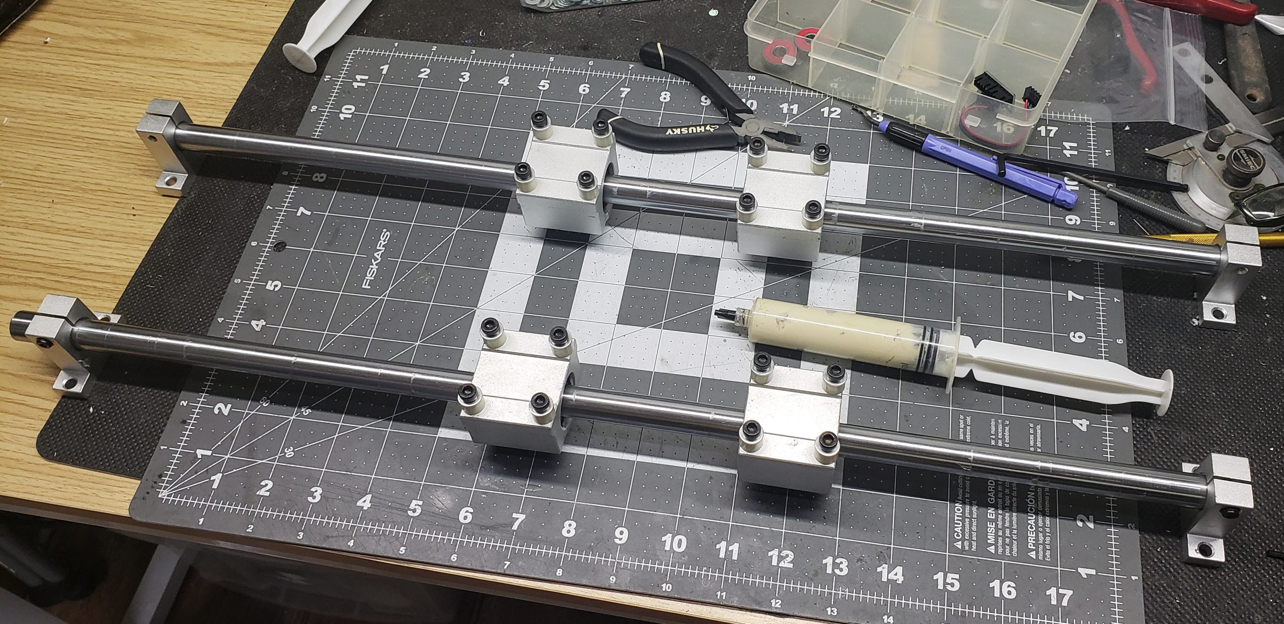
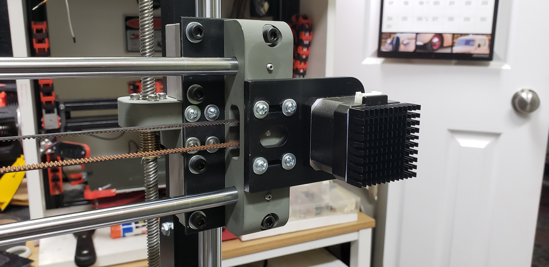
The key element of this part of the design is the rail mounting.
A bearing system of this type is highly sensitive to misalignments, twisting of the rails, and similar issues. Consequently, I never even considered using the standard mounting brackets that come with the rails. You can see them in the photo above — they were only used as temporary stands while I was fine-tuning the bearings.
Using such brackets would require aligning everything across four independent points in all planes. Not only is this a major headache, but in the future, once those four brackets are integrated into the main frame, even the slightest deformation of the frame would throw everything off again!
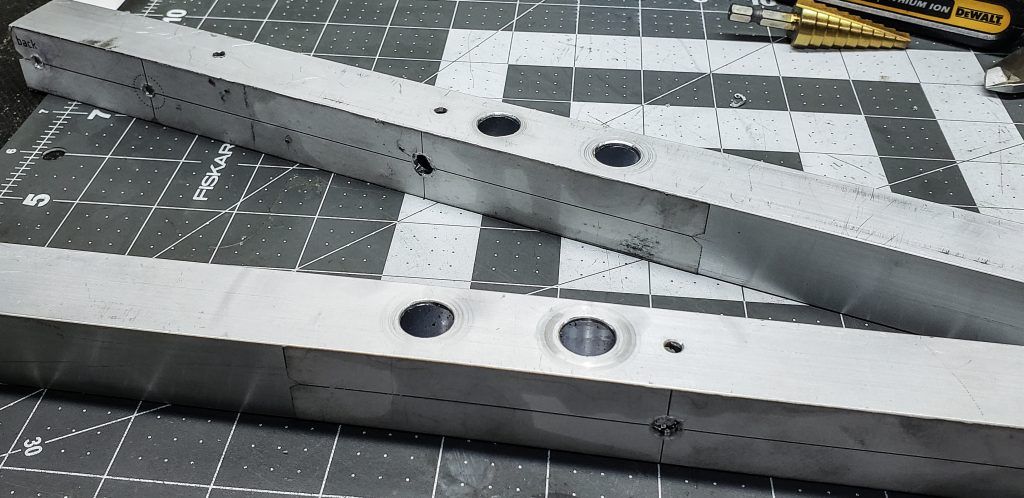
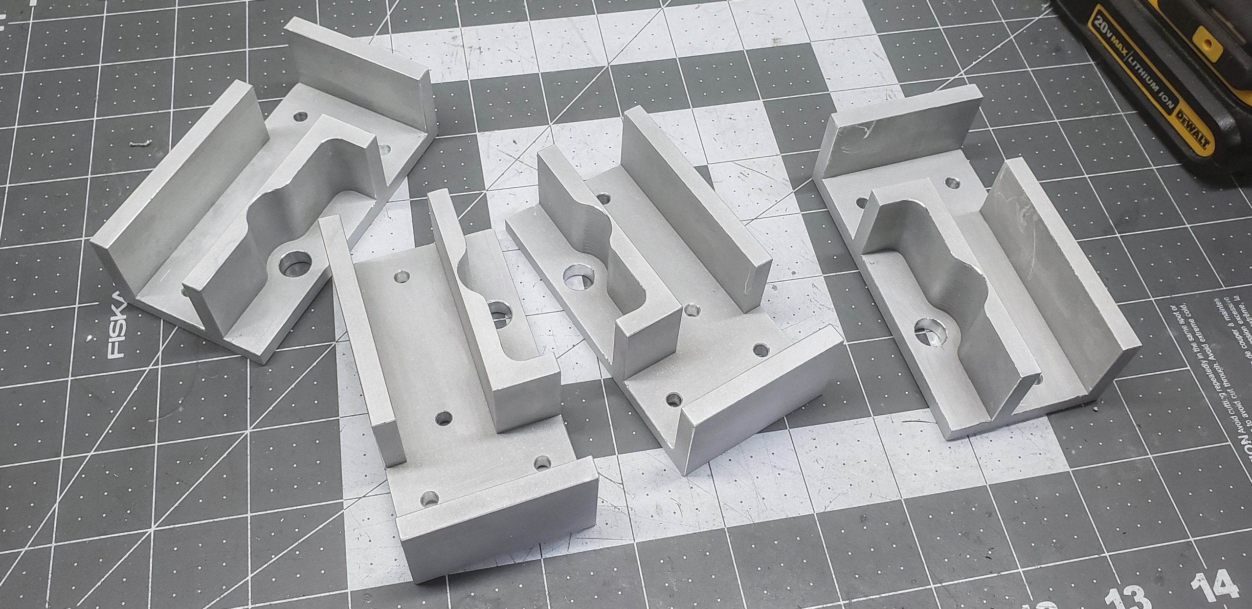
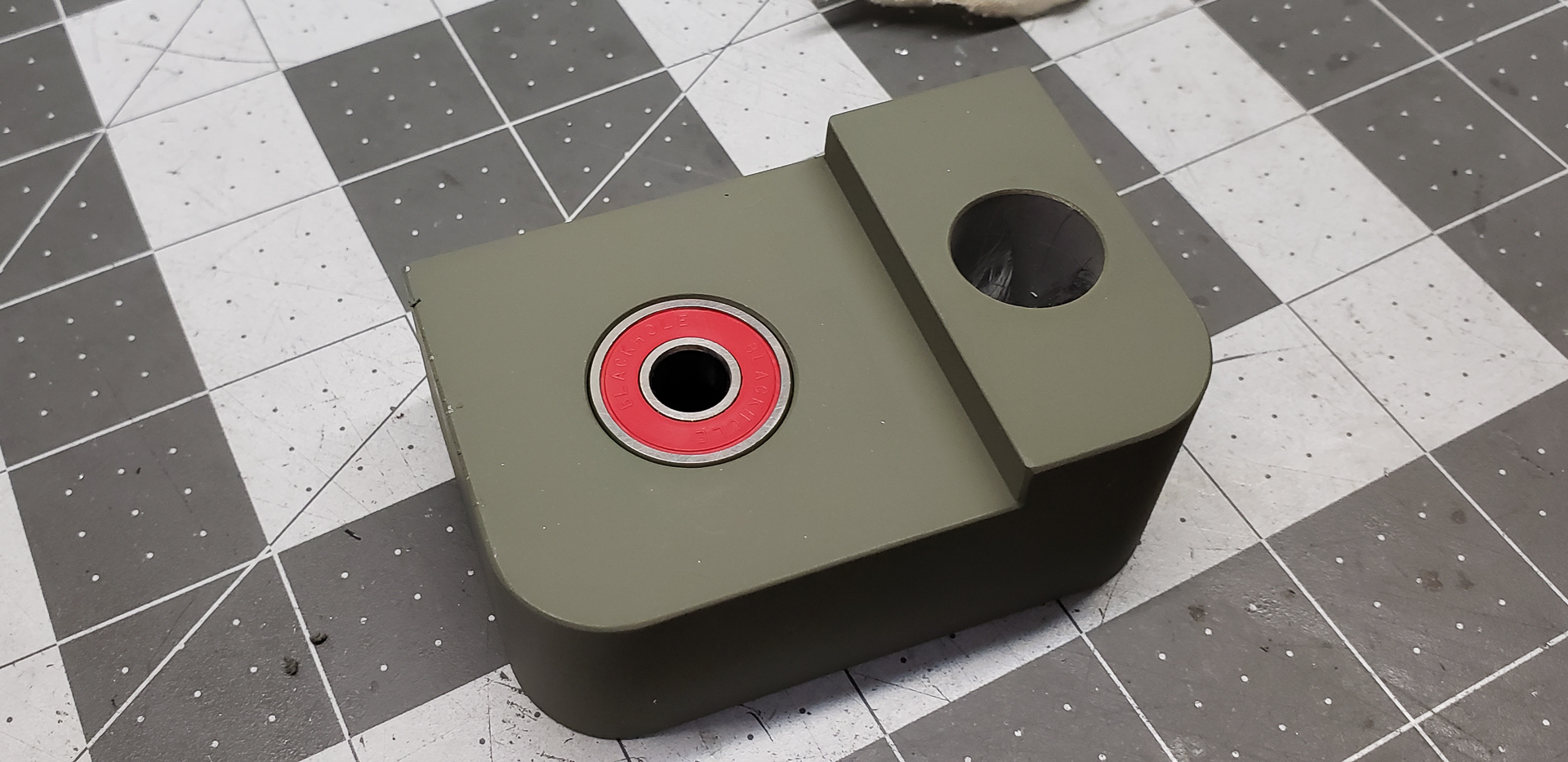
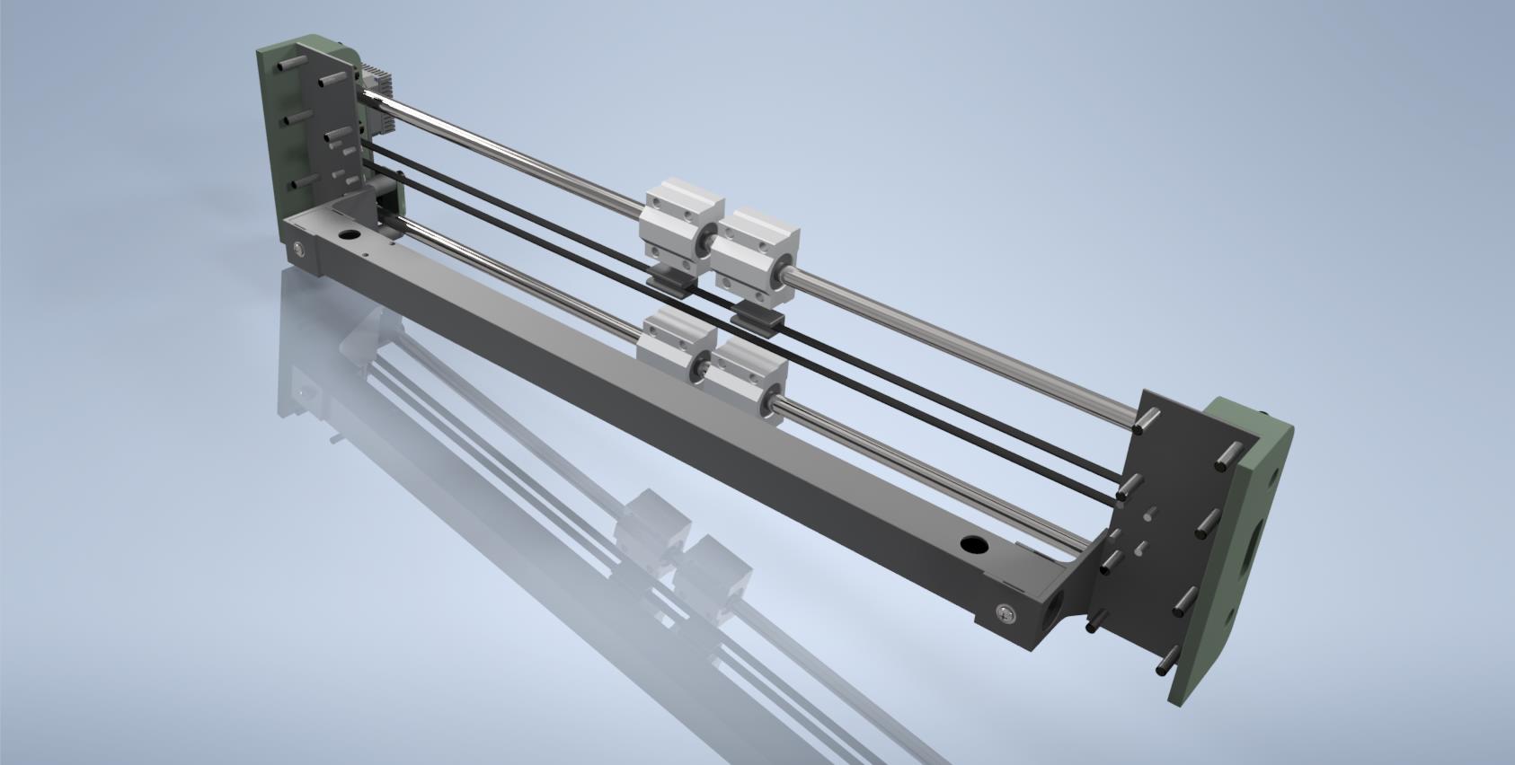
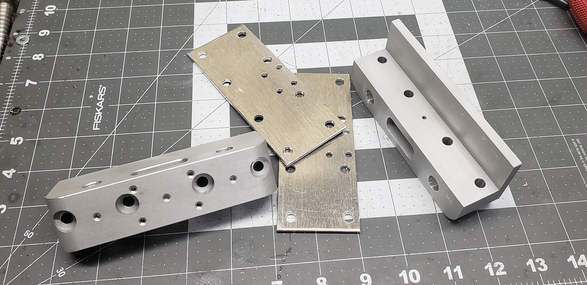
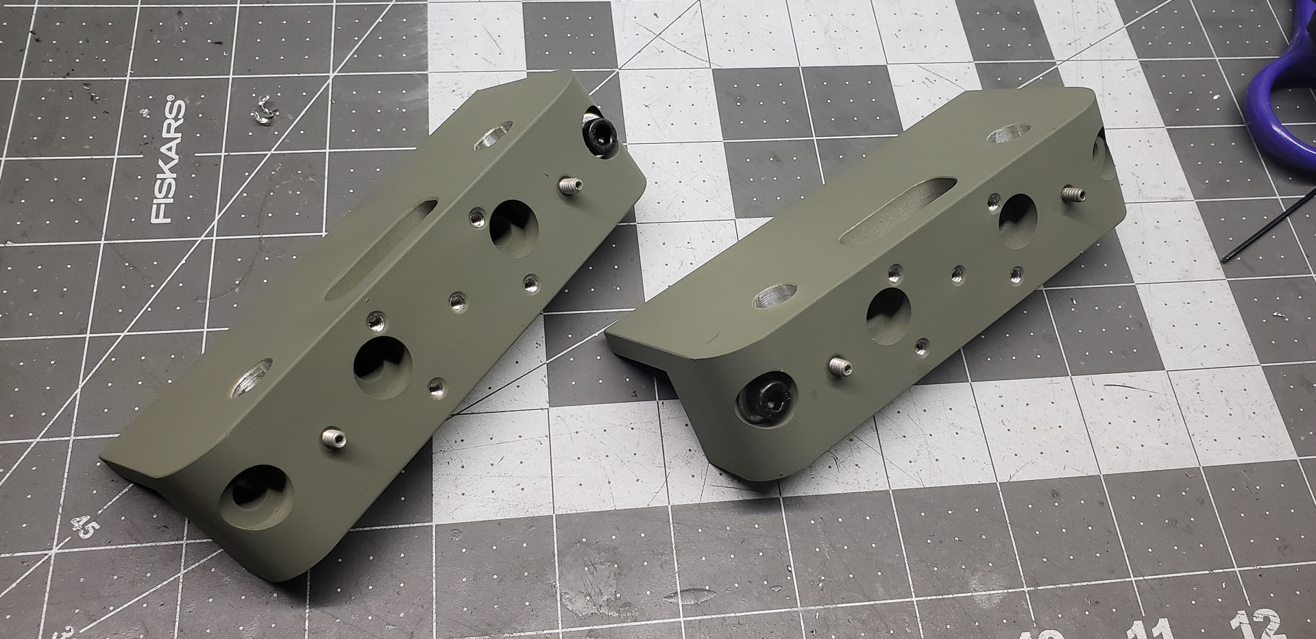
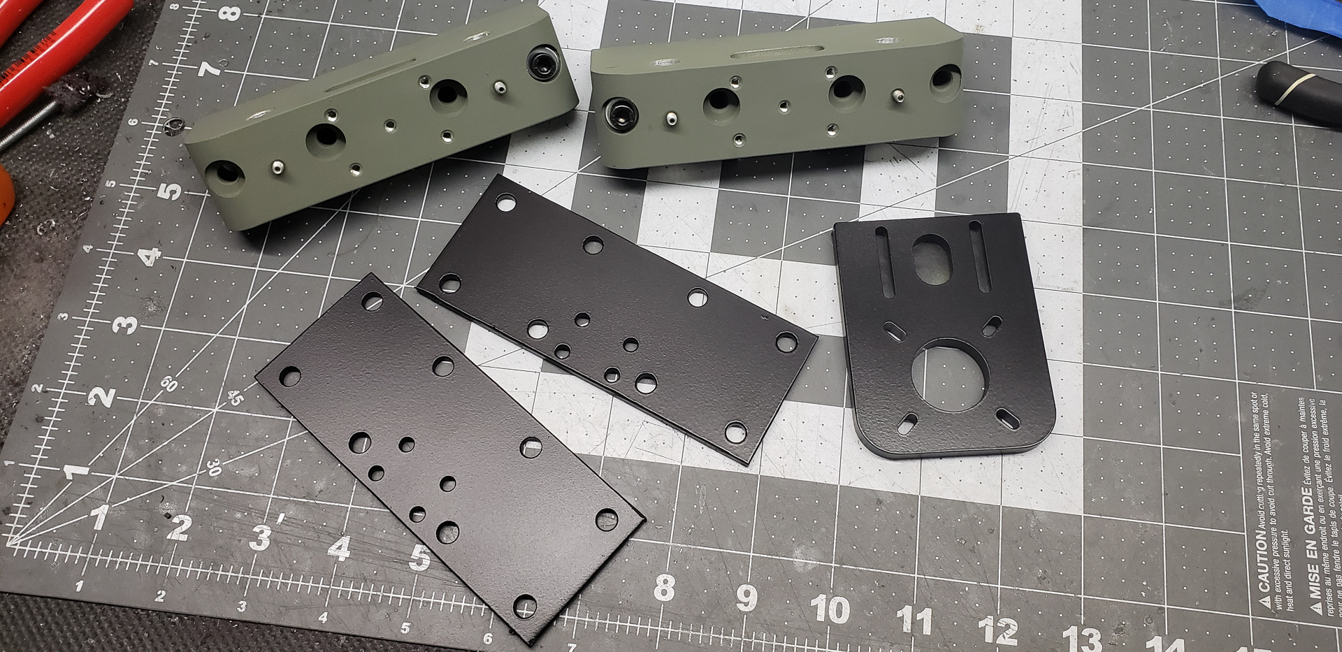
Therefore, I decided to make mounts that would eliminate any potential misalignments not only during assembly but also in the future. The rails would be mounted onto two massive blocks made from solid aluminum:
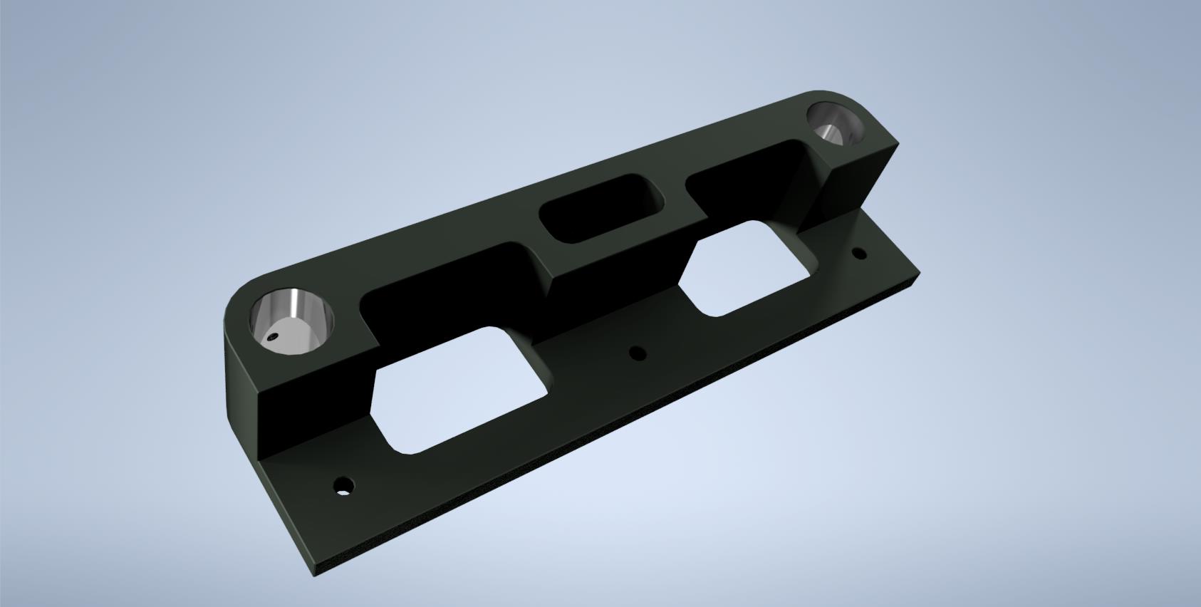
The equal spacing and parallel alignment of the rail mounting holes are ensured by the CNC milling machine itself. All of our machines are certified (with an official document updated every six months) to operate with an accuracy of up to 0.0001 inches (two-thousandths of a millimeter).
Of course, this is far from the pinnacle of global precision standards, but for gunsmithing tasks, it’s more than sufficient. Generally, tolerances here range from 0.01 to 0.001 inches. I honestly can’t remember ever having to deal with tolerances beyond four decimal places.
And let’s not forget we’re talking about a machine the size of a small room. Personally, I can quite literally step into the machine, get comfortable, and even take a nap on its worktable — and it would cradle my couple of hundred pounds with two-thousandths-of-a-millimeter precision.
In short, there are no issues with the parallelism or spacing of the rails. The machine will cut exactly what’s drawn in the model. The remaining concern is the accuracy of the hole diameters for the guide rails. And here, not everything depends on the machine.
Formally, these guide rails are supposed to have a diameter of exactly 16 mm. But the manufacturing facility where they were produced has its own tolerances and standards. The bearing, in turn, is designed to:
But for the mounts, this precision is crucial! The more accurate the mounting holes are, the less play the rails will have, and the higher the parallelism of the rails will be across all planes.
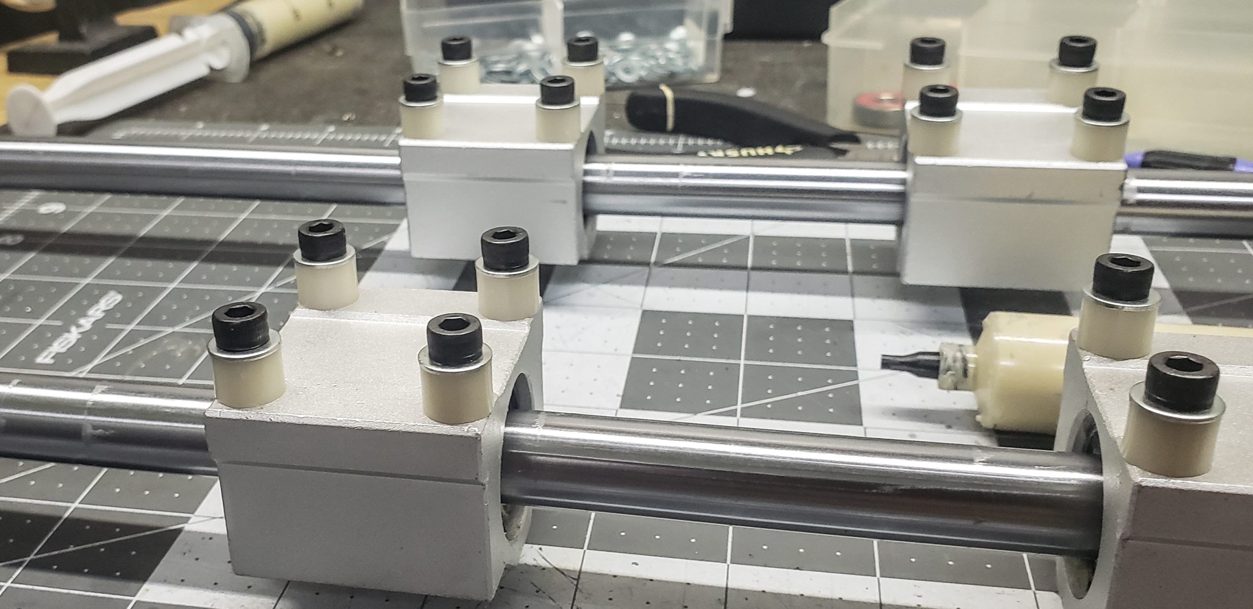
After a few experiments with hole diameters (the rails were actually not precisely 16 mm but somewhere around 16.01–16.015 mm), I achieved my “perfect” mounts:
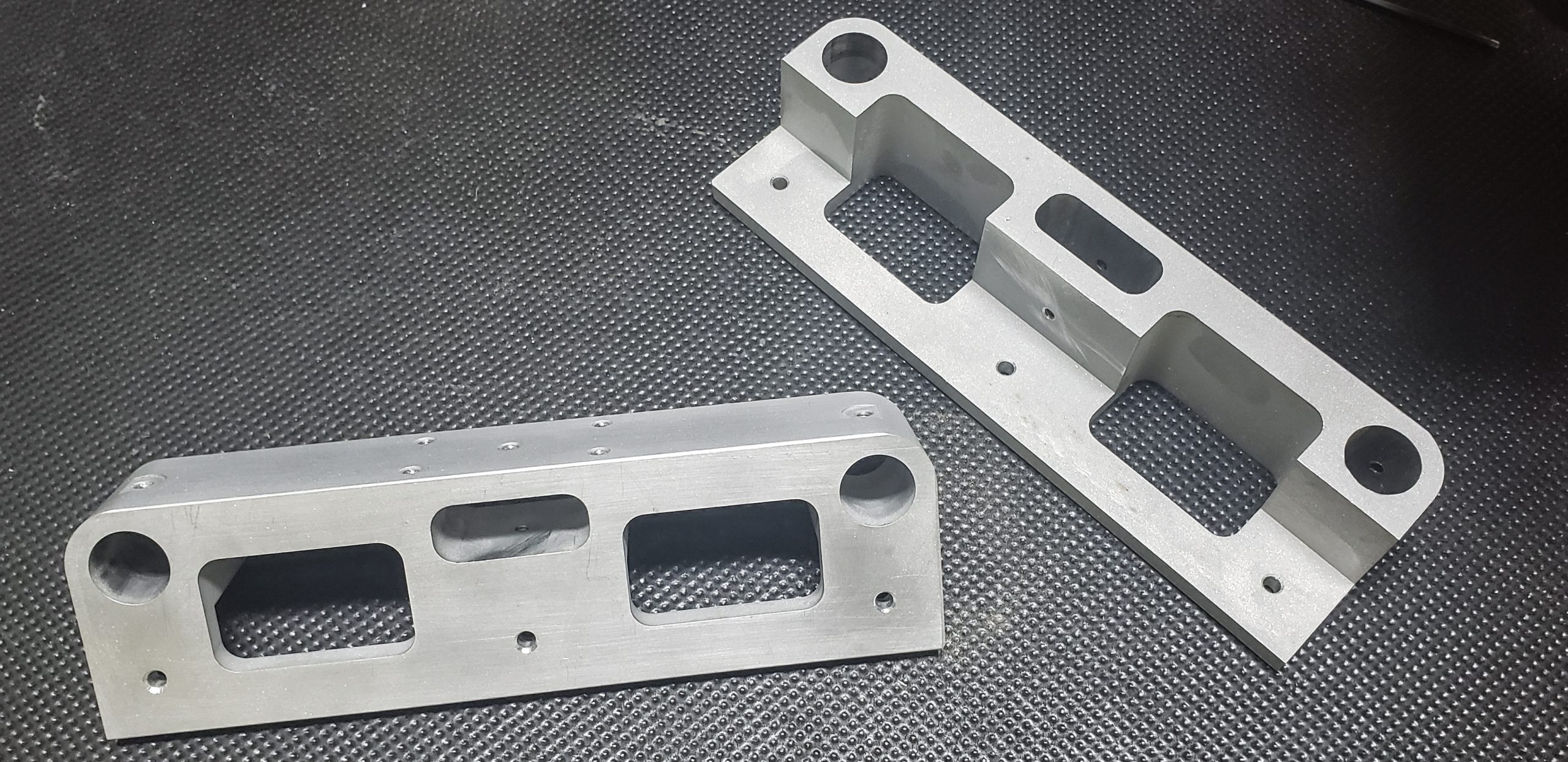
I messed up in just one spot. I should have drilled the holes for the set screws and threaded them first, and only then bored out the guide rail holes. I botched this in the most embarrassing way, and as you can see in the photo, I ended up with a “crown” inside the rail hole around the thread for the set screw… I had to carefully trim it away with a scalpel.
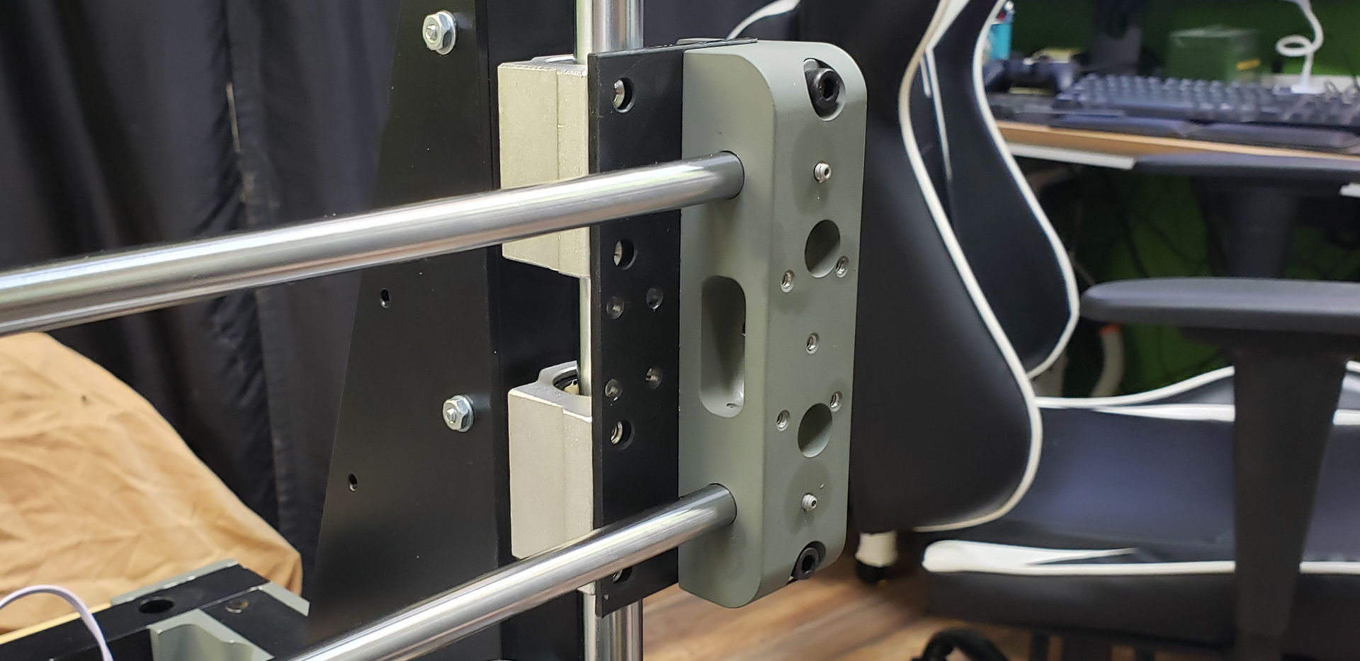
The guide rails for the bearings fit snugly into place without the slightest play. In fact, the set screws in the design are merely a formality. The whole setup holds itself perfectly still, absolutely level, and perfectly perpendicular without any additional fasteners:

Of course, the set screws are mandatory. The setup holds itself reliably only as long as it remains static. Once the bearings start sliding and moving along the rails with a heavy platform on top…
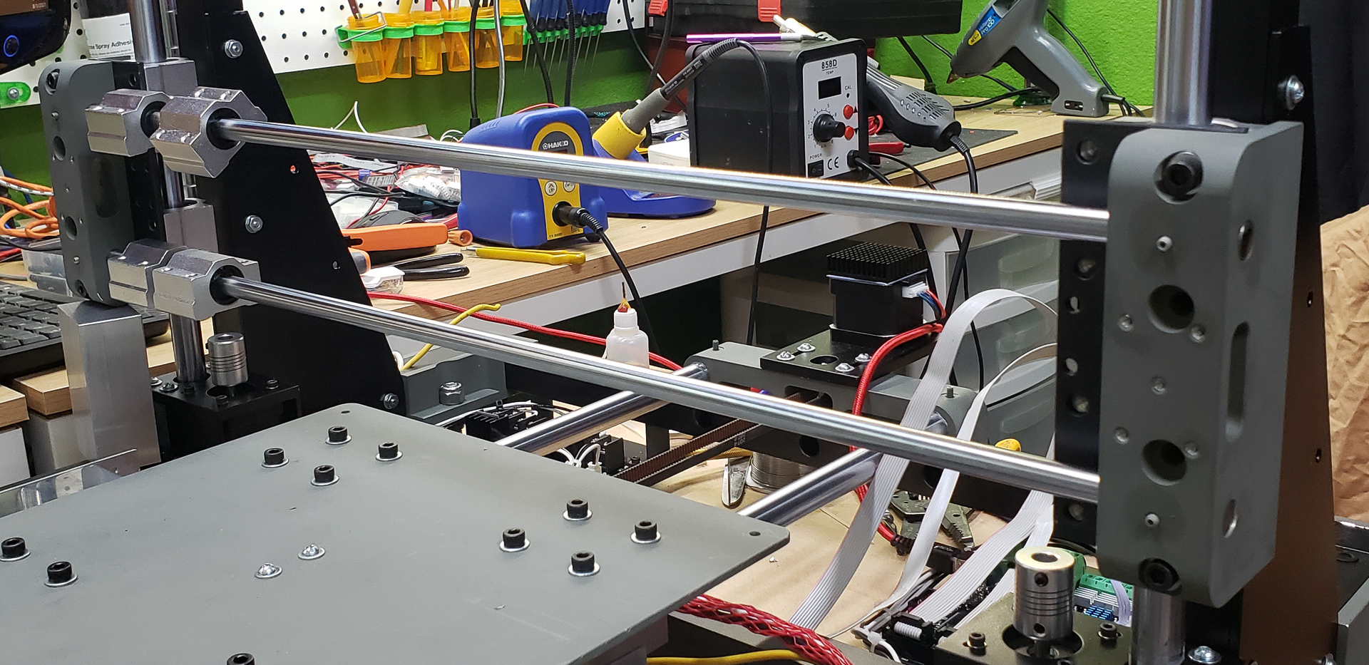
So far, everything is going beautifully and exactly according to plan. It’s time to see how well it all moves.
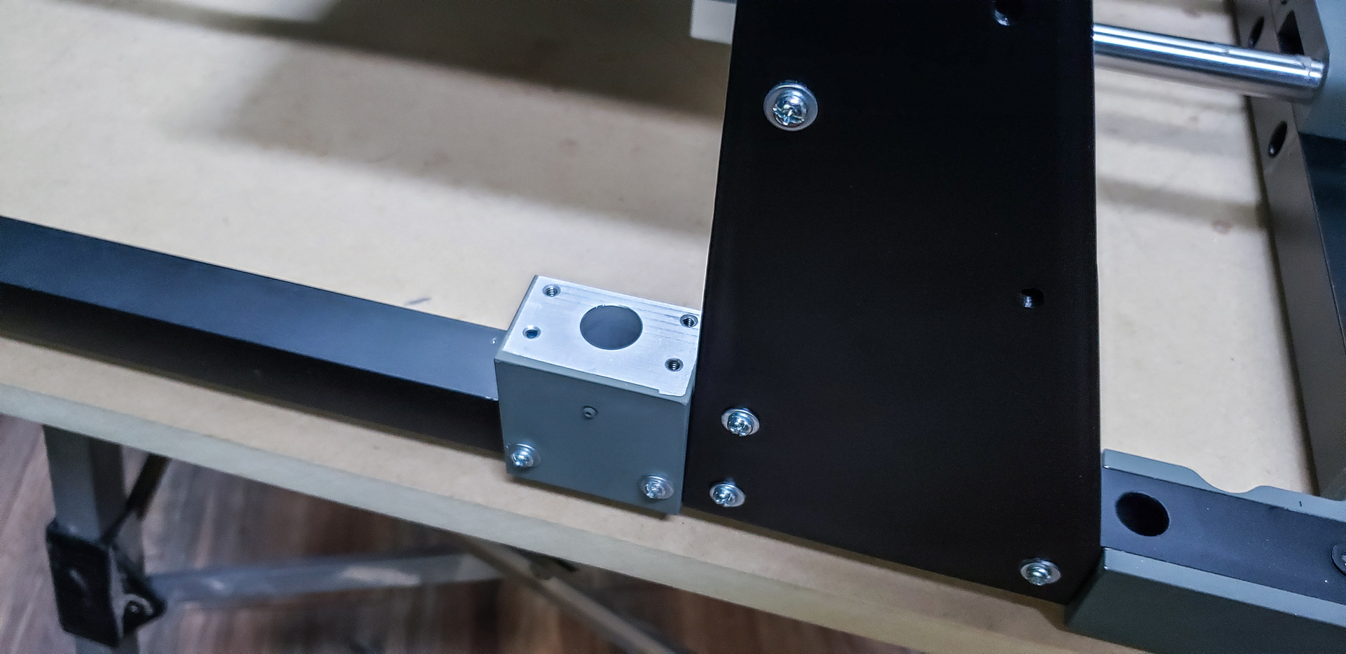
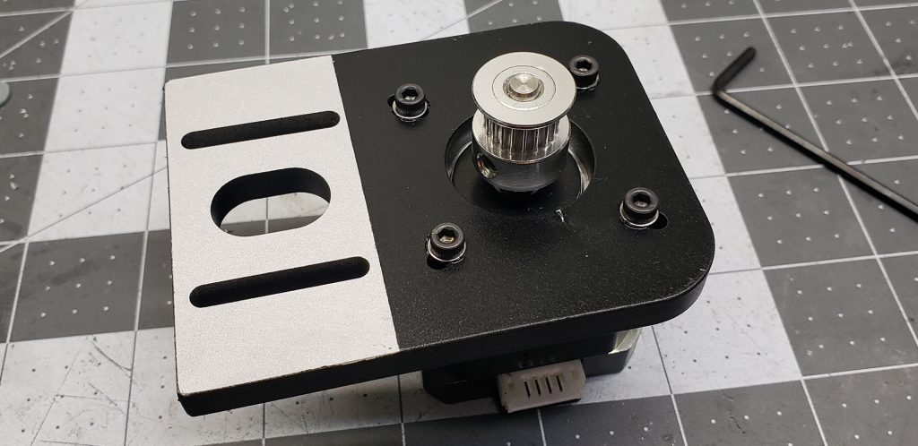
To get this printer axis moving, a motor needs to be attached. For this purpose, the rear mount has threaded holes for securing the motor platform:
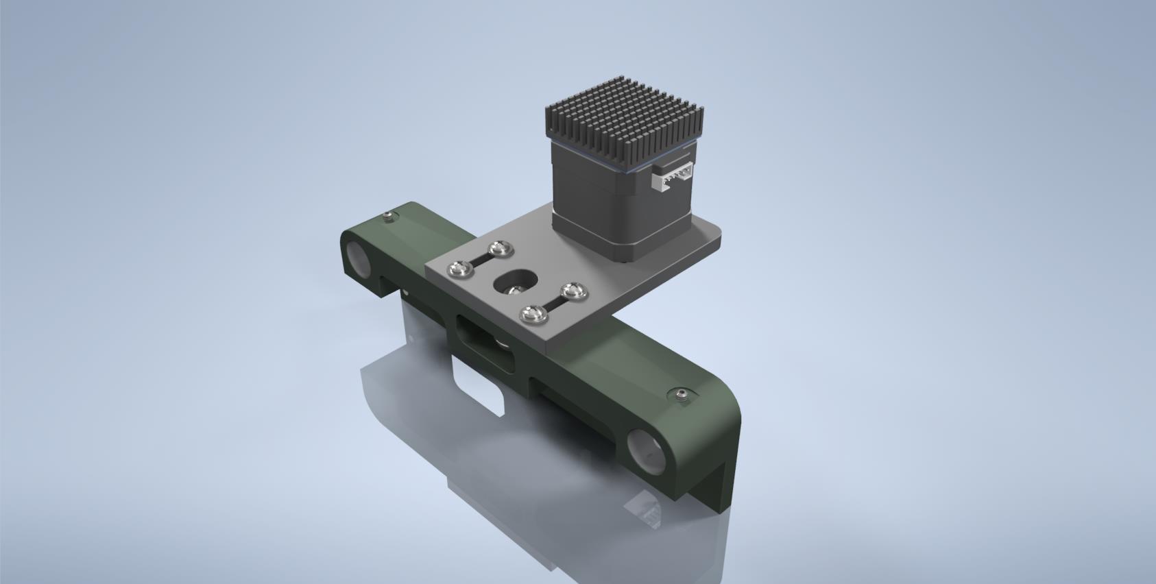
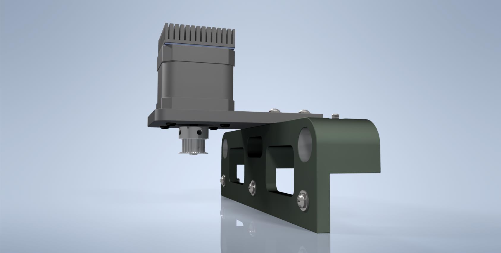
In fact, both mounts for the guide rails are completely identical — this made the design and manufacturing process simpler and faster. As a result, the mounting holes for the motor platform are present not only on the rear mount of the axis but also on the front, where they aren’t really needed. But don’t worry, those holes will find their use eventually…
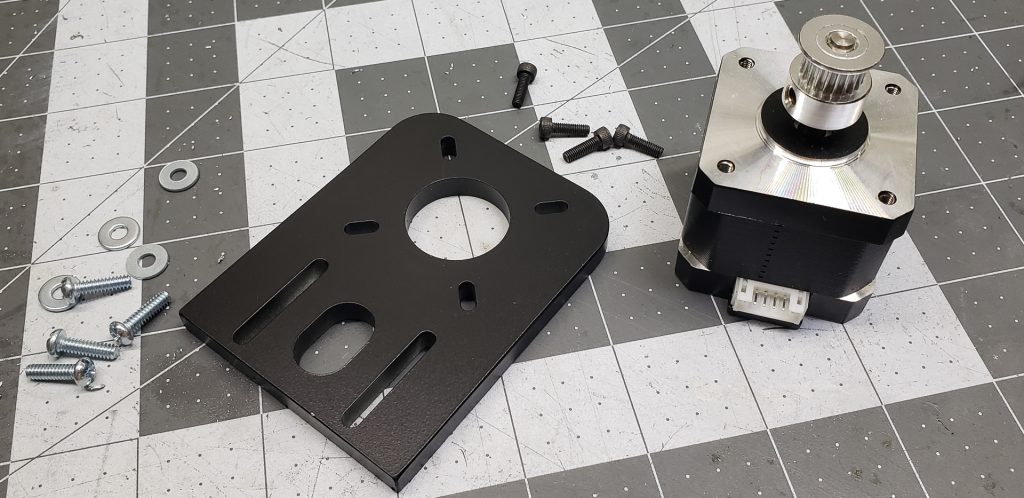
The motor mount was made from a quarter-inch-thick plate.
I found this material in the metal enthusiast’s den. A grim-looking shaggy fellow — reminiscent of Leontiev circa 1980 — dug around in a corner of the shed and pulled out a quarter-inch strip of material, slightly chewed up along the edges by some wild cutters and covered in a layer of dust about a finger thick. It wasn’t a particularly long strip, but it was enough to cut out the motor mounts:
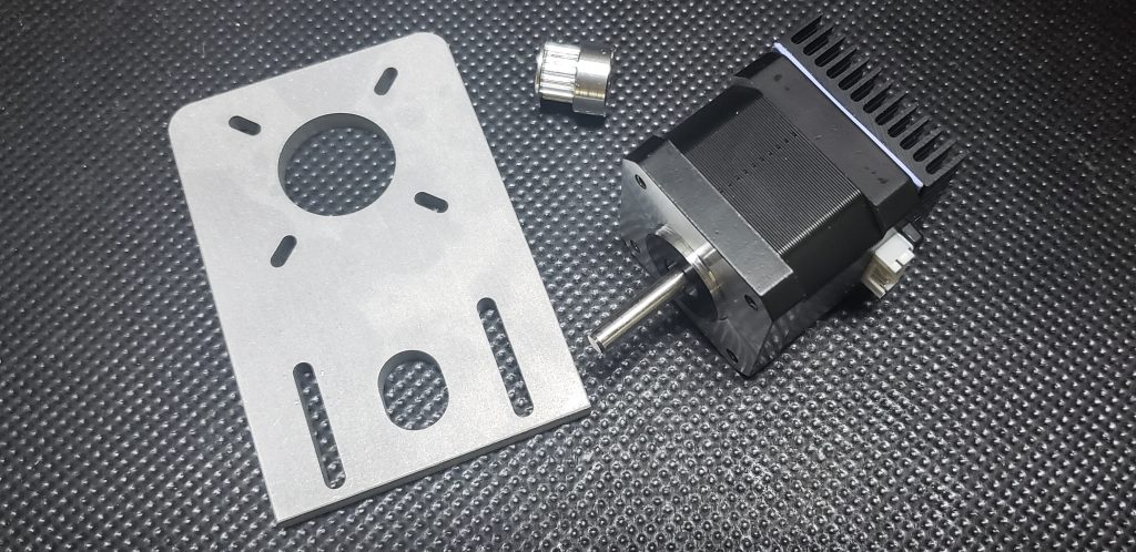
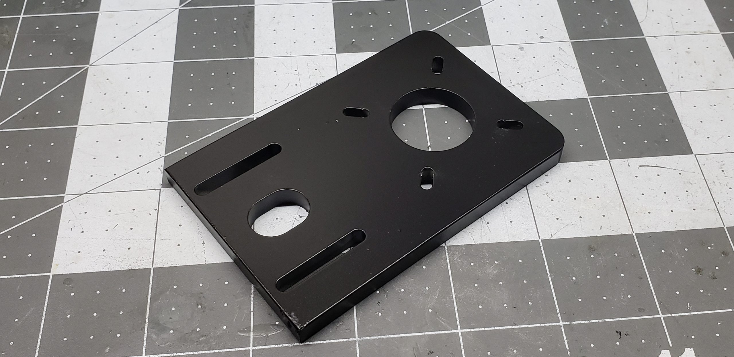
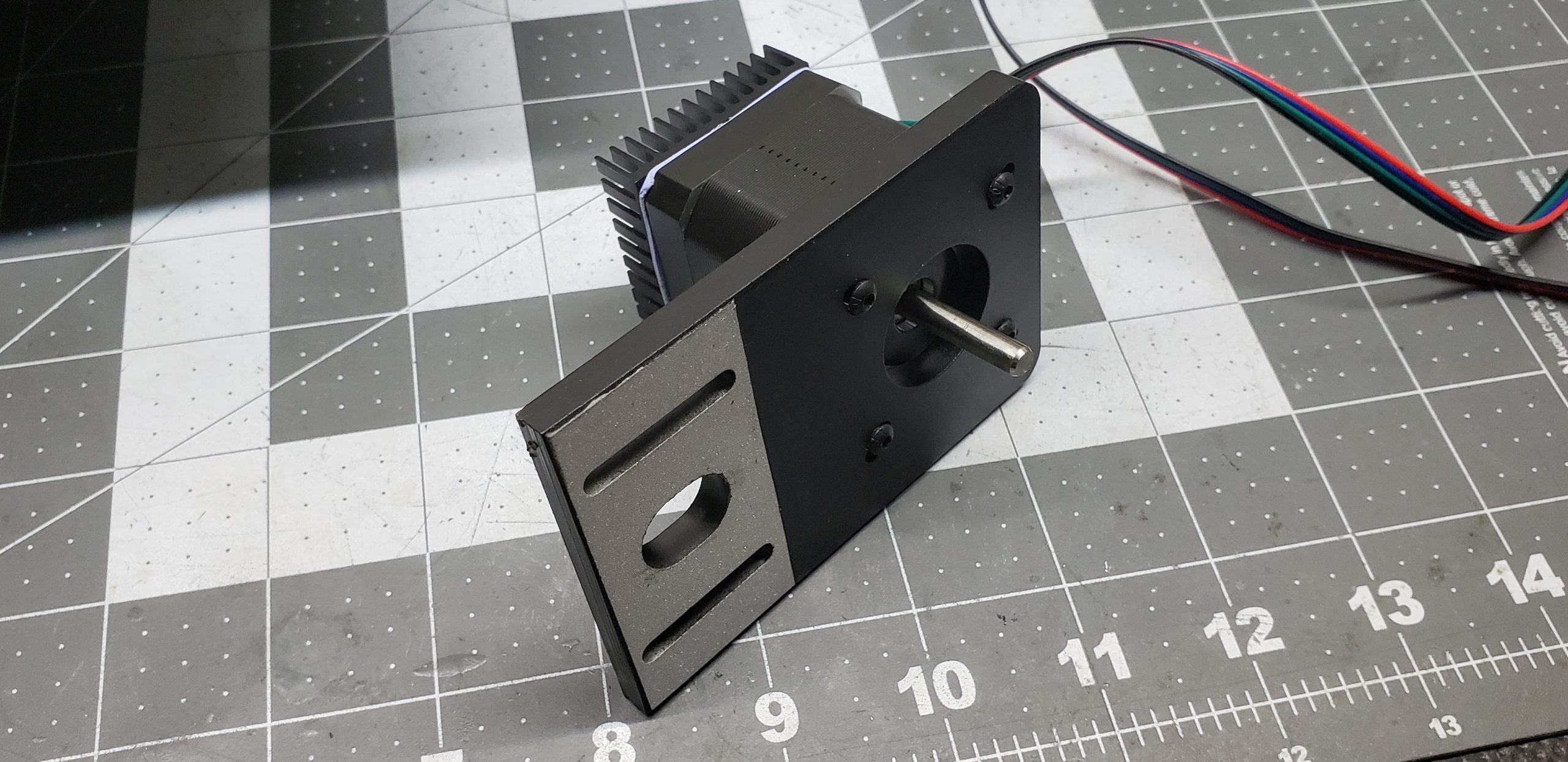
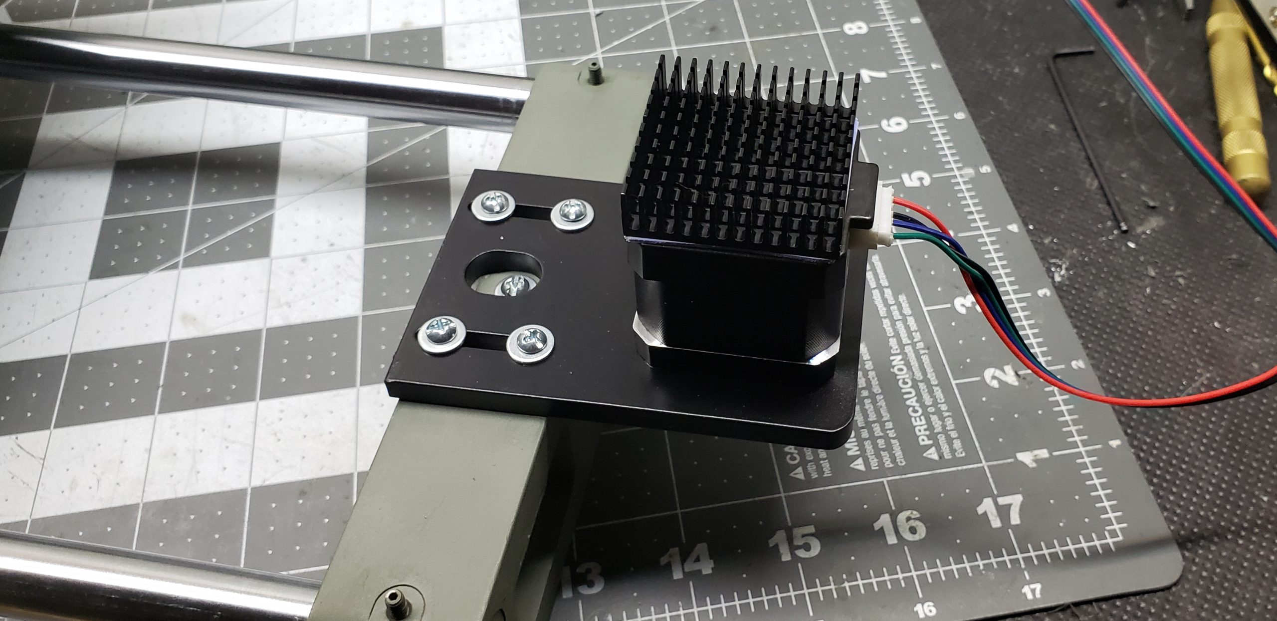
Of course, the holes in the plate weren’t drilled at home on a drill press — they were made using the same CNC mill at work. And the result looks quite professional.
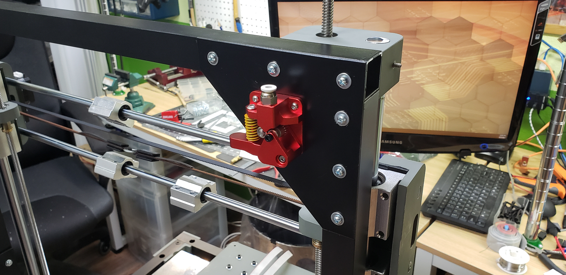
Another crucial element needed to be added to the design before attempting any movement. This part is almost invisible in renders and photos, but it’s there — and it’s exceptionally important. Without it, nothing would move properly.
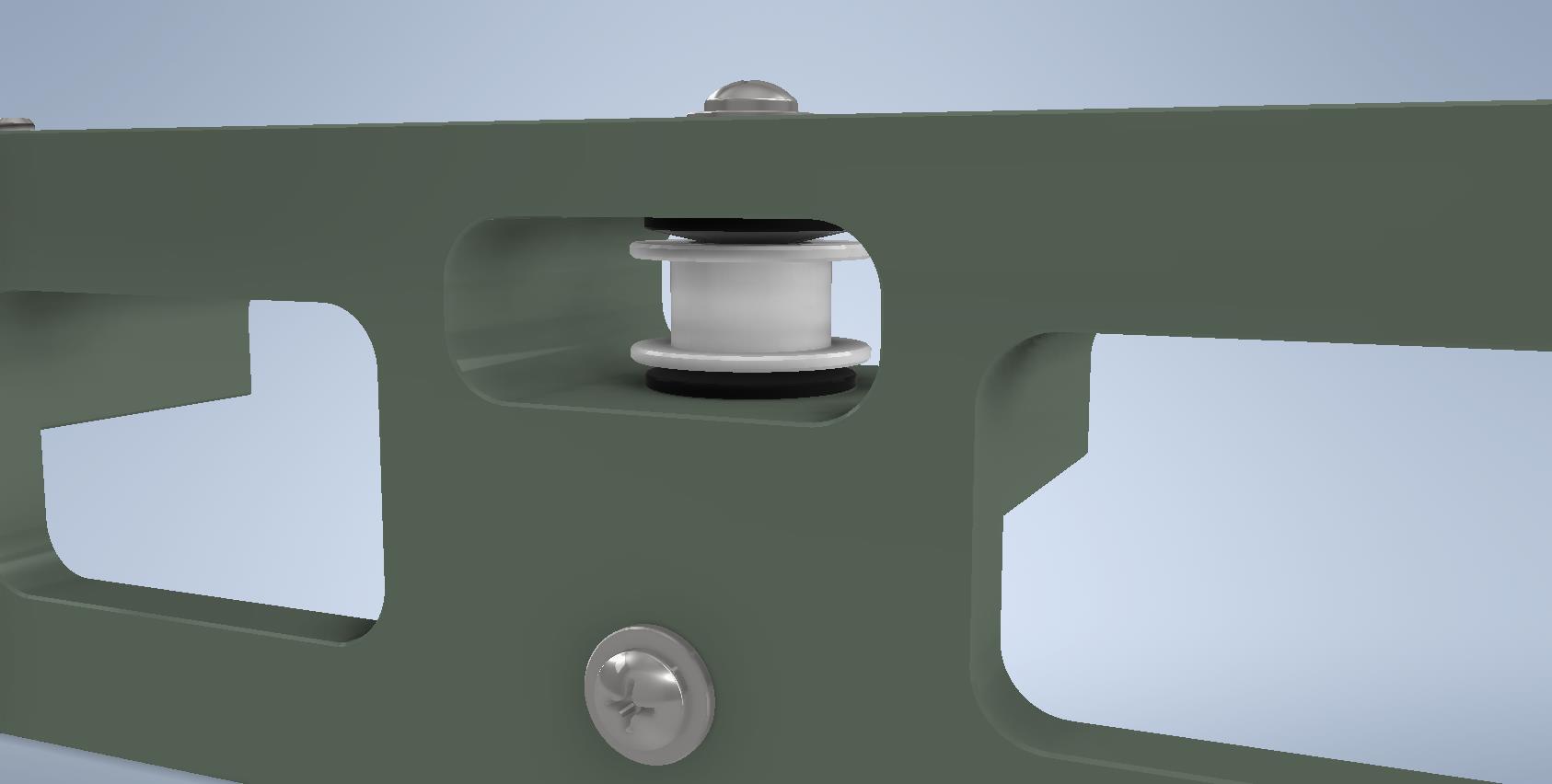
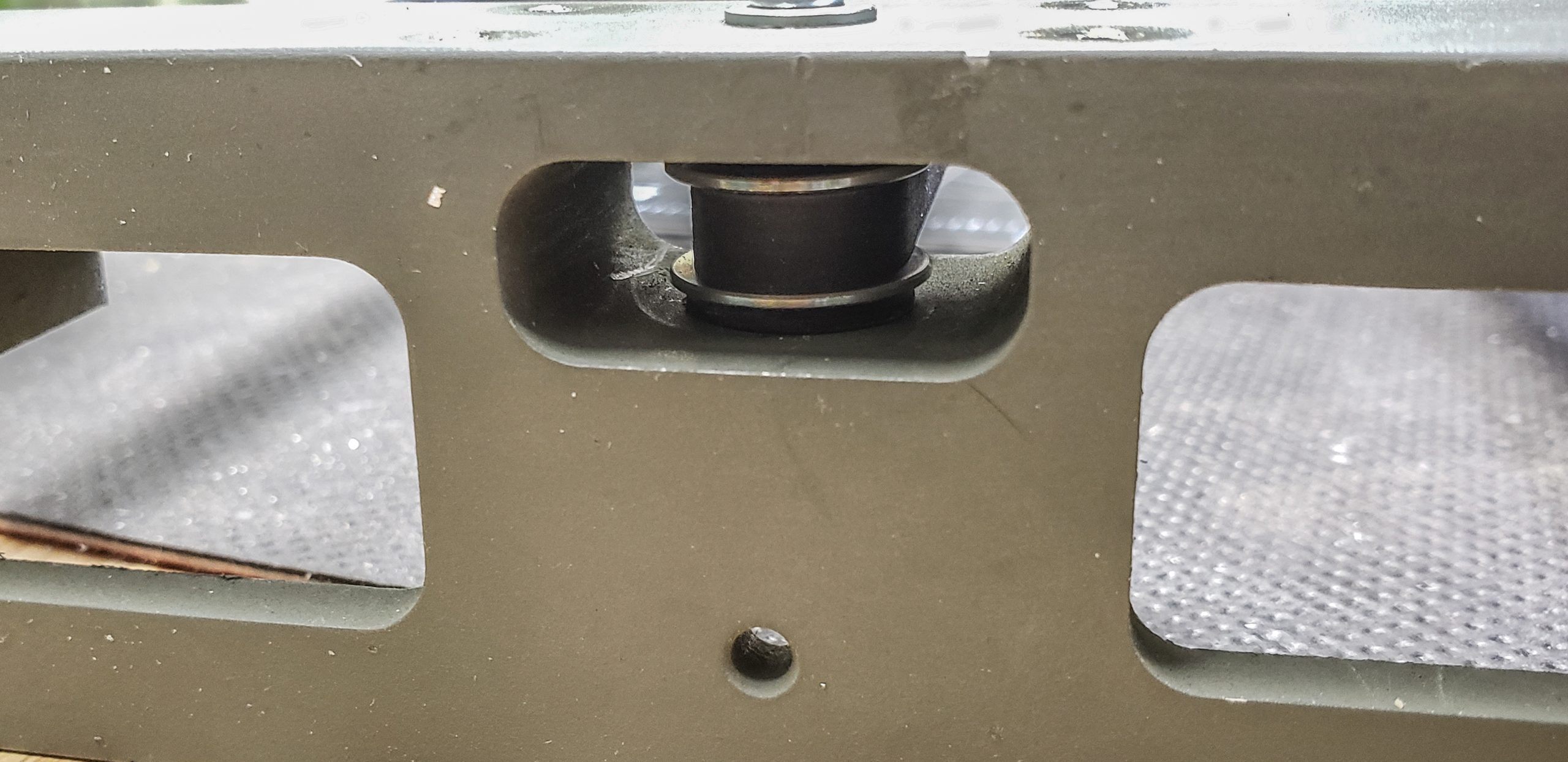
The tensioner pulley for the drive belt. You can see it tucked away in the dedicated mounting niche:
It’s not as simple as it seems. And it’s definitely not as simple as how 99% of DIY makers and even Chinese manufacturers build it into their printers. Typically, they take a standard 2GT belt pulley and bolt it directly onto the frame. That’s exactly how it was on my Black Widow printer… For added frustration, the pulley height is often adjusted using a sandwich of nuts and lock nuts.
Maybe I’m being overly picky, but seeing those nuts and the inner bearing sleeve grinding directly against the cheap screw’s threads makes my blood boil. Especially since the screw diameter almost never matches the bearing diameter exactly. To keep the pulley from wobbling, they tighten it with another nut — which usually ends up locking the bearing. So, the belt just slides over a jammed pulley… Bar-bar-ians! I hate it!
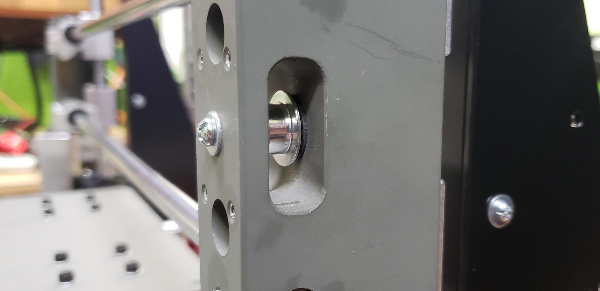
First, the pulley mount is designed so that it’s always vertically aligned with the center of the guide rails. This completely eliminates the need to adjust it for the belt to run parallel to the axis. It simply has no other option.
Second, the pulley’s mounting axis is secured both from the top and the bottom. A threaded hole goes entirely through the niche, which eliminates any vertical misalignment of the pulley (a common issue that leads to loosening and slipping of the belt).
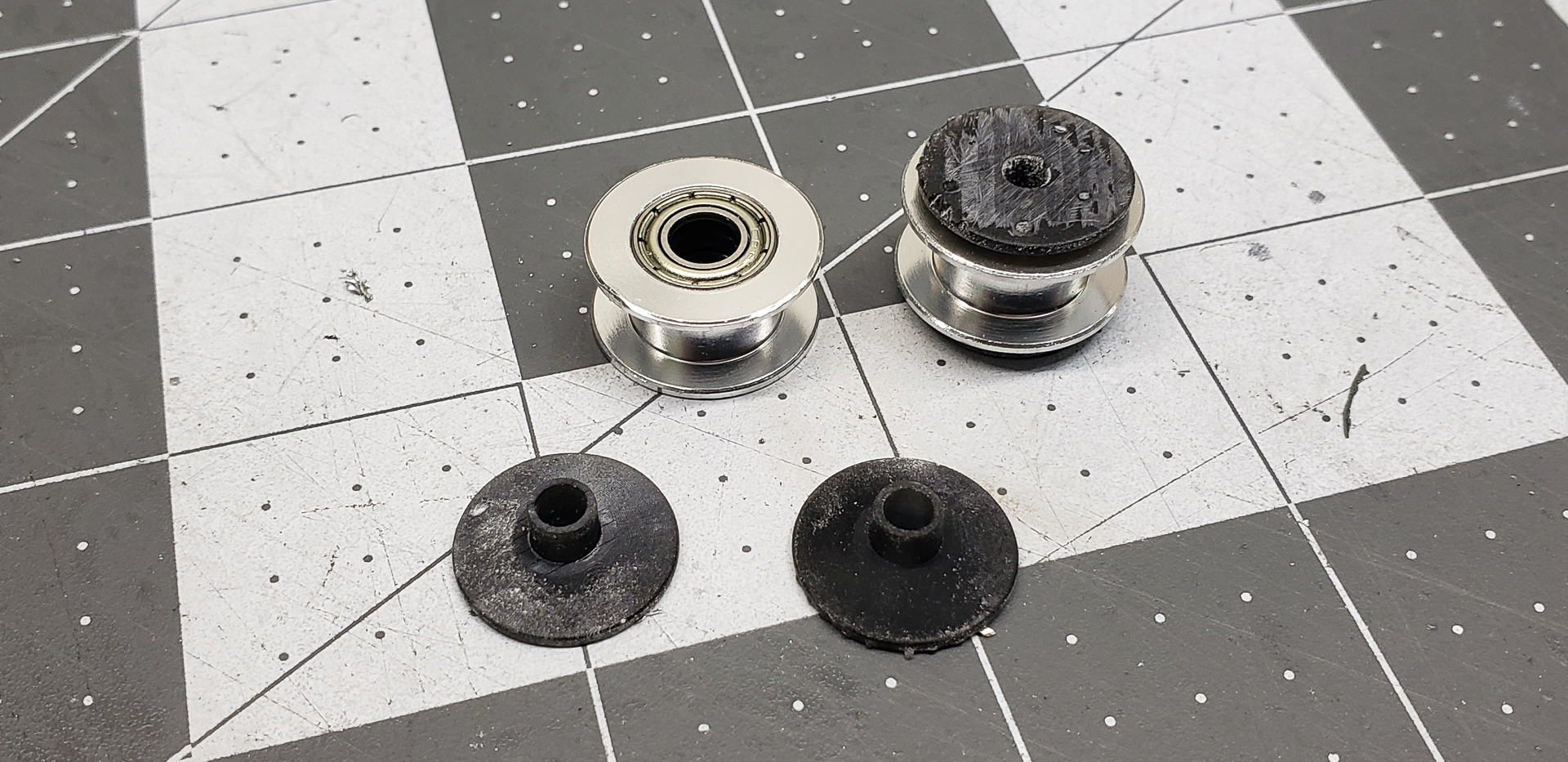
Third, the pulley’s mounting screw doesn’t interact directly with the bearing at all. Instead, special inserts are placed between them. The outer diameter of these inserts matches the inner diameter of the bearing sleeve perfectly, while their inner diameter matches the screw diameter precisely.
No adjustments are required, no undue pressure is applied, nothing tilts, and everything rotates smoothly and freely:
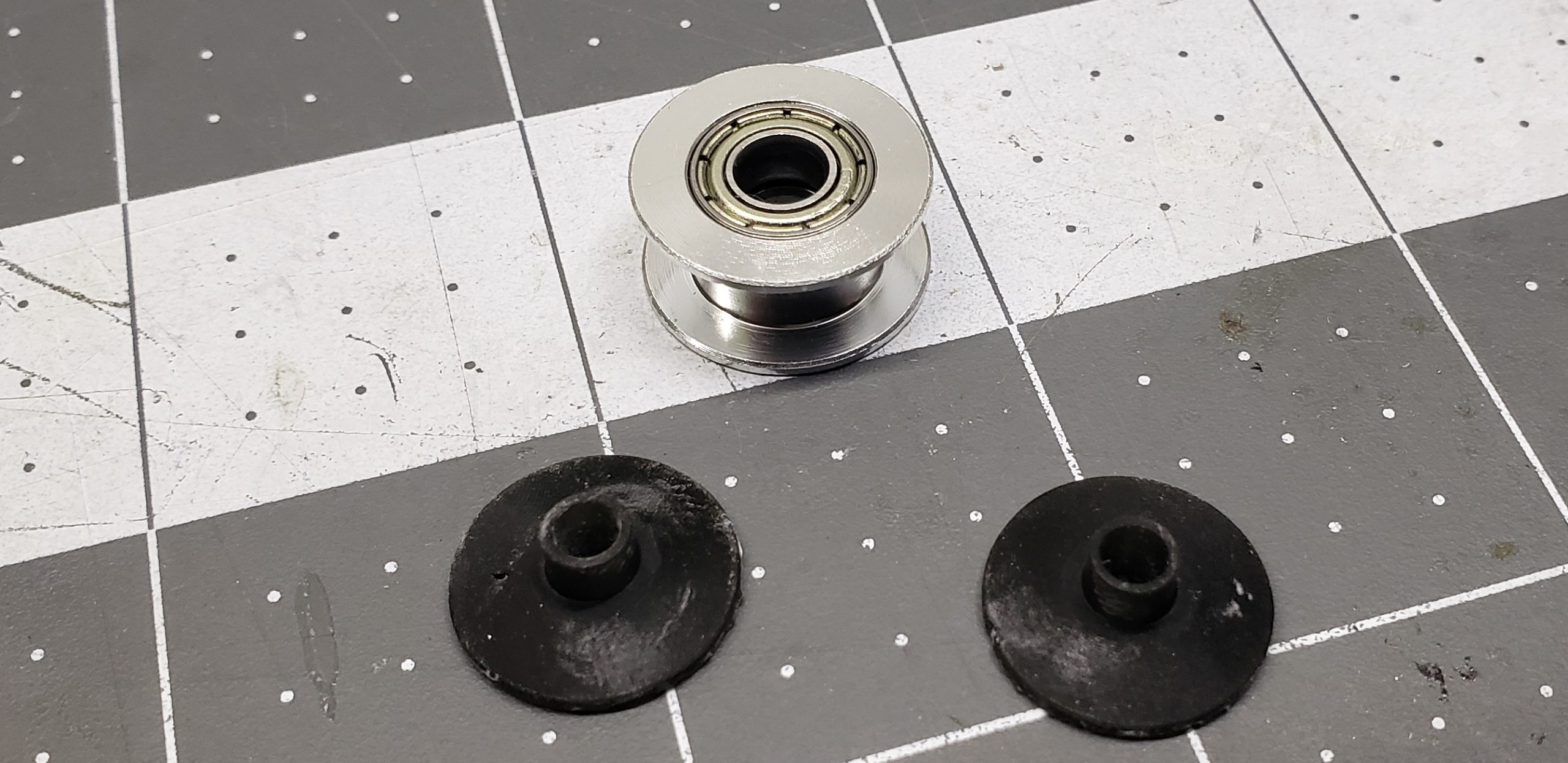
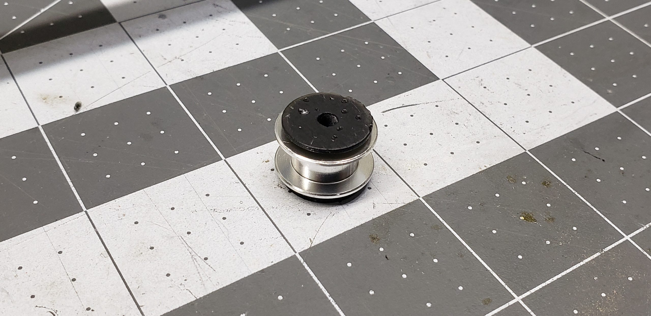
The faces of the inserts were intentionally left unfinished at first. During installation, I sanded them down with fine-grit sandpaper to ensure there was no gap between them and the mounting niche:
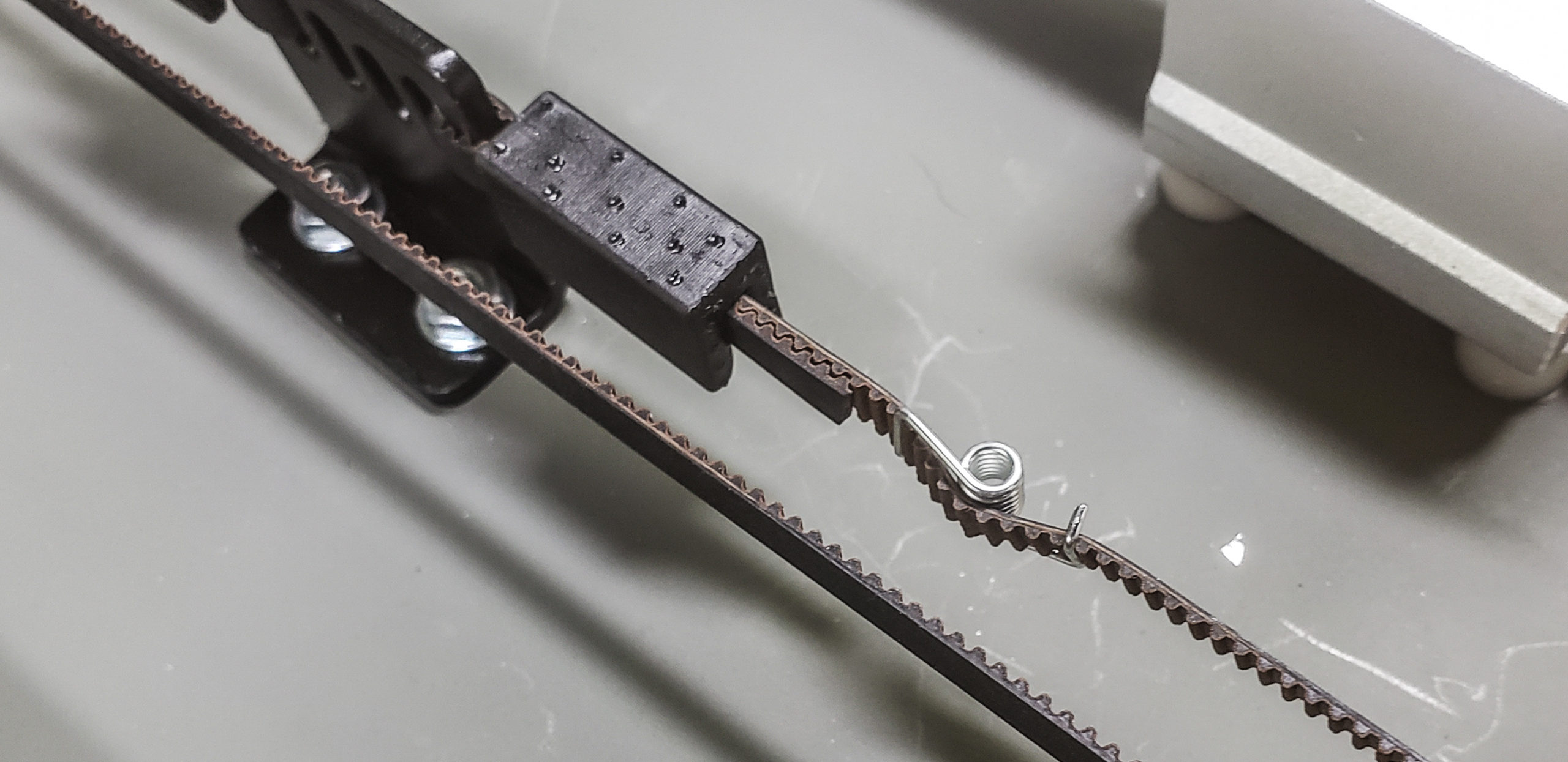
Everything is almost ready for the big move. All that’s left is to add the drive belt.
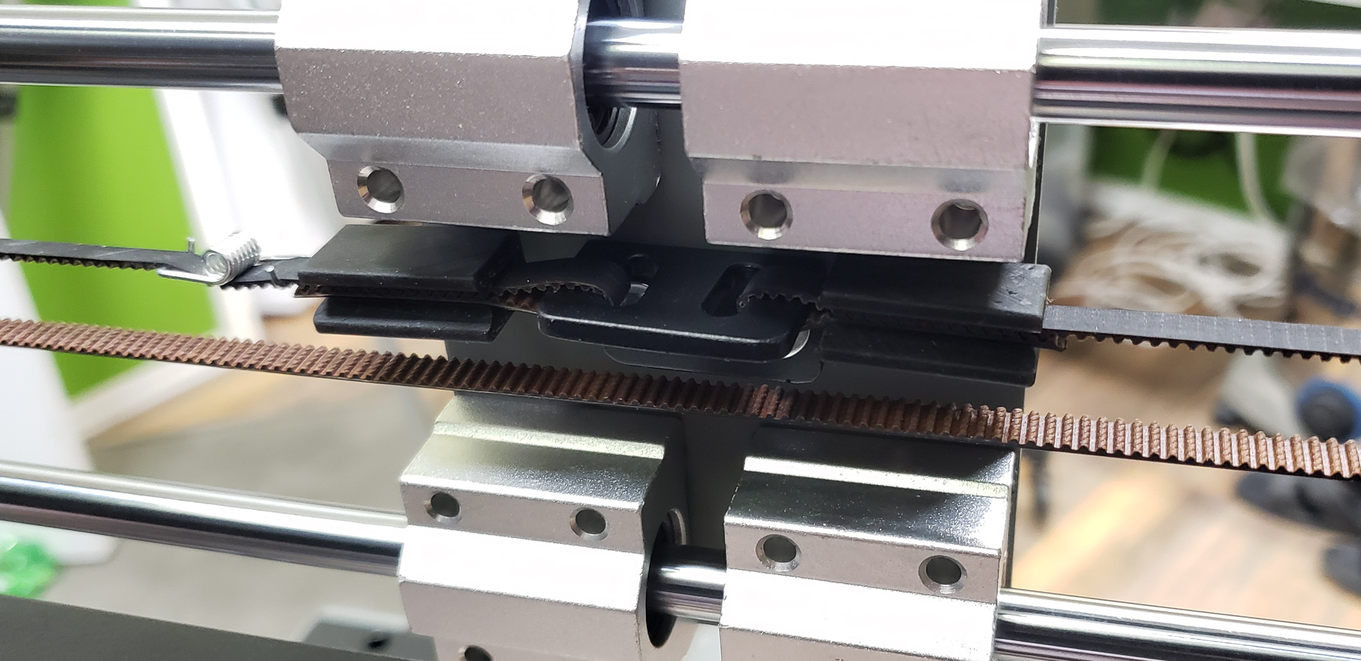
To avoid fiddling with clamping plates and “ties” constantly, I “invented” special locks for securing and tensioning the belt ends:
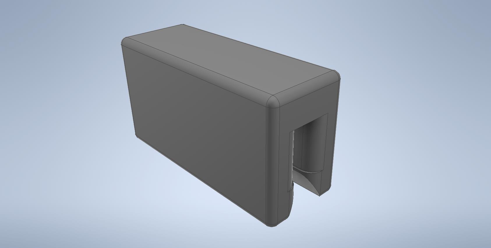
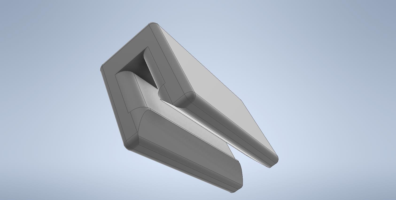
Essentially, the belt grips itself by meshing its own teeth together. The locks simply prevent the belt tails from splaying apart. It’s like a rough approximation of a zipper. Reliable, easy to secure, and just as easy to remove:
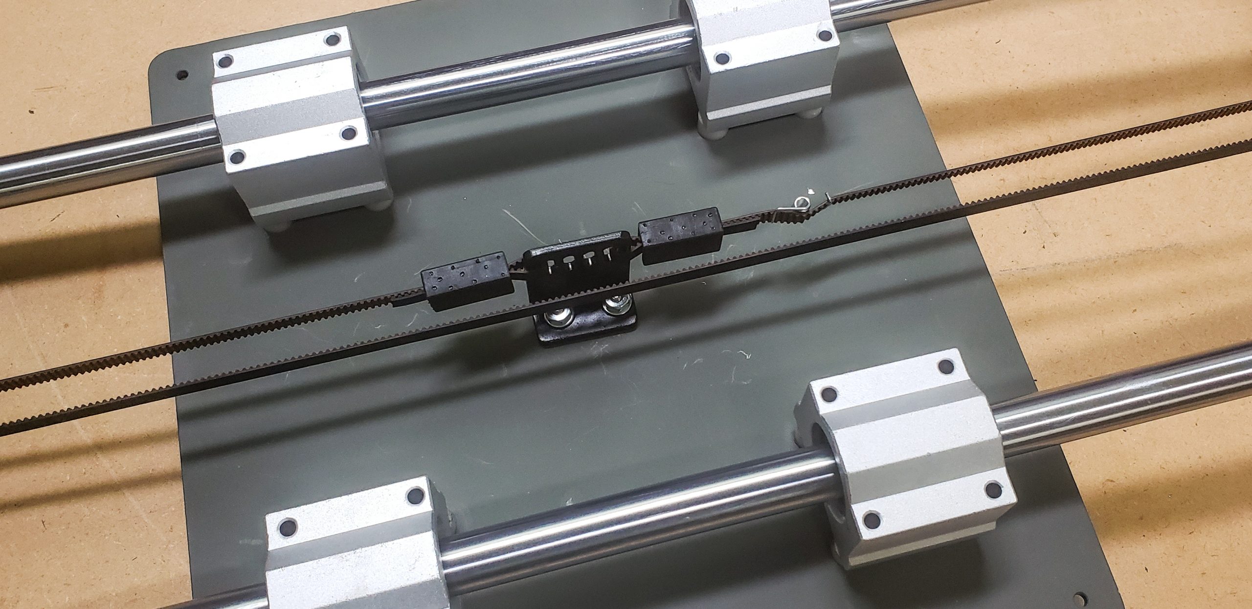
That’s it. Time to make it move.
Here’s the very first almost-independent motion this device made:
The clicking you hear when the table changes direction? That’s me acting as the limit switch.
At that time, a proper controller for the printer was still in transit. But I was eager to get the table moving. For such situations, I had thrown together a simple universal stepper motor driver some time ago. It’s very basic yet incredibly handy:
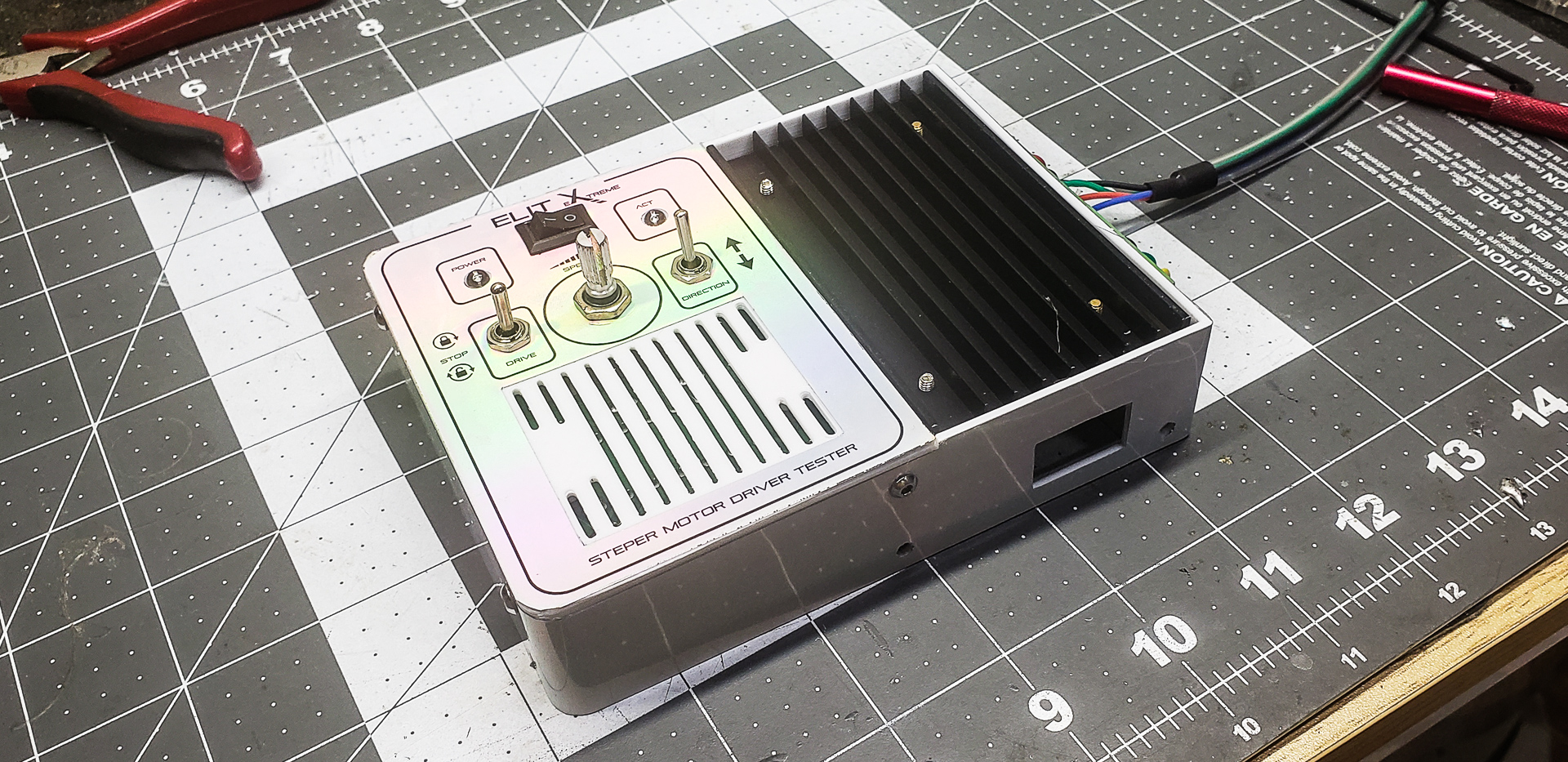
The left toggle switch is a three-position switch. The bottom position is momentary, functioning like a simple button. The top position behaves like a standard toggle switch, and the middle is off. This allows me to make the motor spin either continuously, hands-free, or “at my command” — press to move, release to stop. This is especially useful in unpredictable situations, which are a regular occurrence with prototypes. It gives me a chance to pull my finger back and immediately stop movement before something crashes dramatically. At the same time, if nothing dangerous is expected, I can flip the switch up, put the controller down, and tinker freely with a screwdriver or other tools.
The center dial controls the rotation speed.
The second toggle to the right of the dial controls the direction of movement — clockwise or counterclockwise. That’s the clicking sound you hear in the video.
And now, the final part of this chapter…
The main load-bearing frame of the printer was constructed in parallel with its motion axes. I don’t see much point in dedicating a separate post to its assembly.
The part of the frame directly related to the Y-axis consists of just four crossbars assembled into a square:
The crossbars themselves were straightforward. Regular 1×1-inch aluminum profiles with 1/16-inch wall thickness. Cutting, marking, drilling, deburring, edge smoothing, priming, and painting — nothing special:
However, more effort was intentionally put into their corner joints than usual.
I was absolutely against using the popular “furniture” brackets often favored by DIY builders. For some reason, they’re always the go-to choice when it comes to square aluminum profiles:
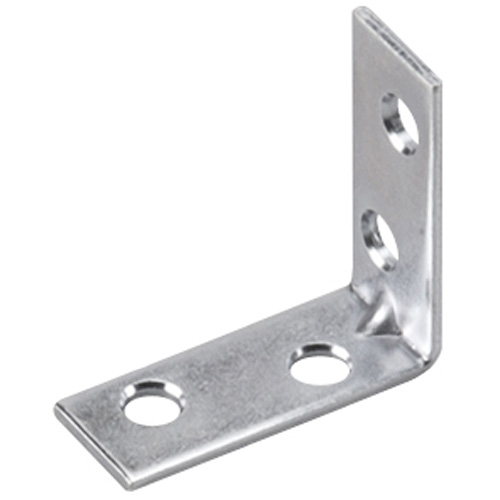
I understand they’re the most accessible and cheapest option. But such brackets are absolutely not designed for this purpose.
No way! Not happening! Aside from their atrocious appearance — which can make any DIY project look like it’s held together with duct tape and sticks — these brackets make it nearly impossible to maintain precise angles between crossbars. Not to mention, the strength of the resulting connection is laughable.
OK, time to invent our own solution… For example, a solid block of high-quality aluminum that connects the crossbars at a guaranteed right angle and holds them in position without loosening over time, even under dynamic loads:

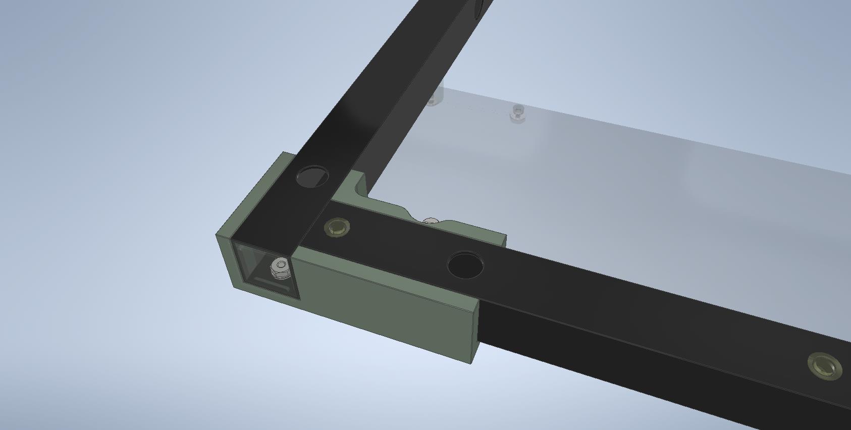
I distinctly remember seeing similar ready-made mounts available for sale somewhere. But for the life of me, I can’t recall where or in what context. I spent an entire day scouring the internet… Ultimately, I had to sacrifice a couple more precious hours on the CNC mill:
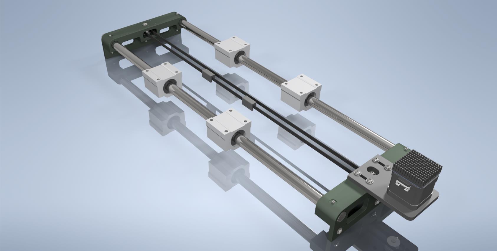
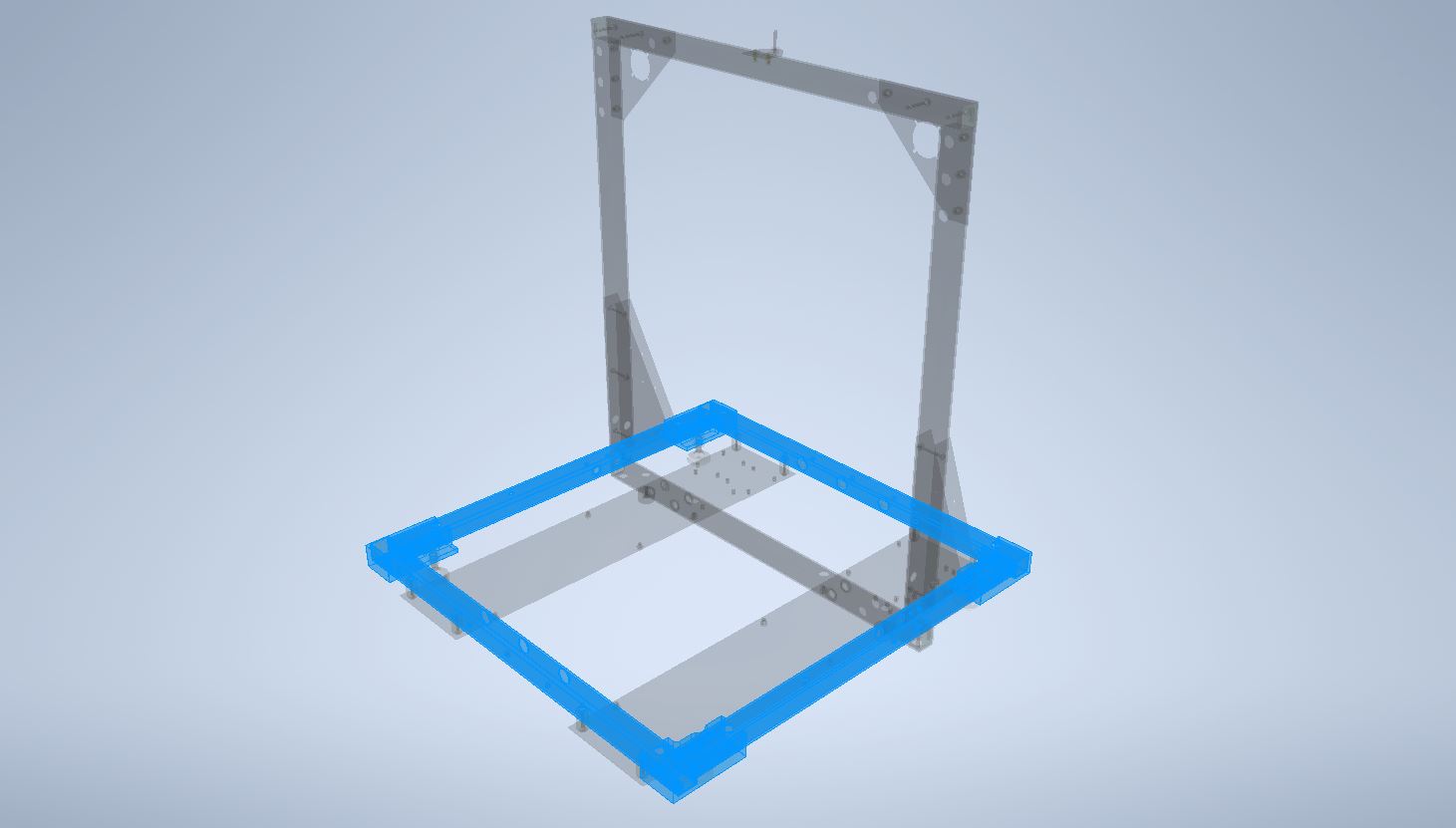
Now the entire Y-axis assembly, including its frame segment, can be put together:
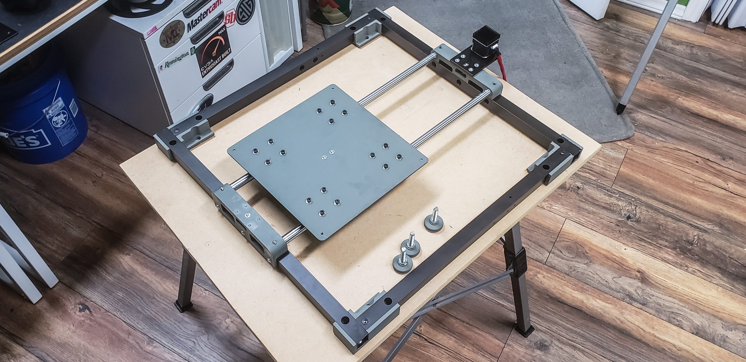
The funny thing is, in the end, I can’t confidently say whether the frame supports the assembly of the rails and motor or if it’s the other way around. Both components turned out to be incredibly self-sufficient, sturdy, and resistant to deformation. Honestly, if it weren’t for the “rubbery” drive belt and the feeble NEMA 17, this setup could have been a decent hobby-grade metal milling machine…
Z-axis
Unlike the Y-axis, the printer’s main frame plays a much more significant role in the context of the Z-axis. Here, you can’t rely on the components of this part of the structure to align themselves.
Attention had to be given to every single detail and connection. It was crucial to ensure that the vertical Z-axis was perfectly perpendicular to the Y-axis. In theory, almost any deformation of the printer’s geometry could later be compensated for in the firmware, but that would automatically mean that something had already gone wrong.
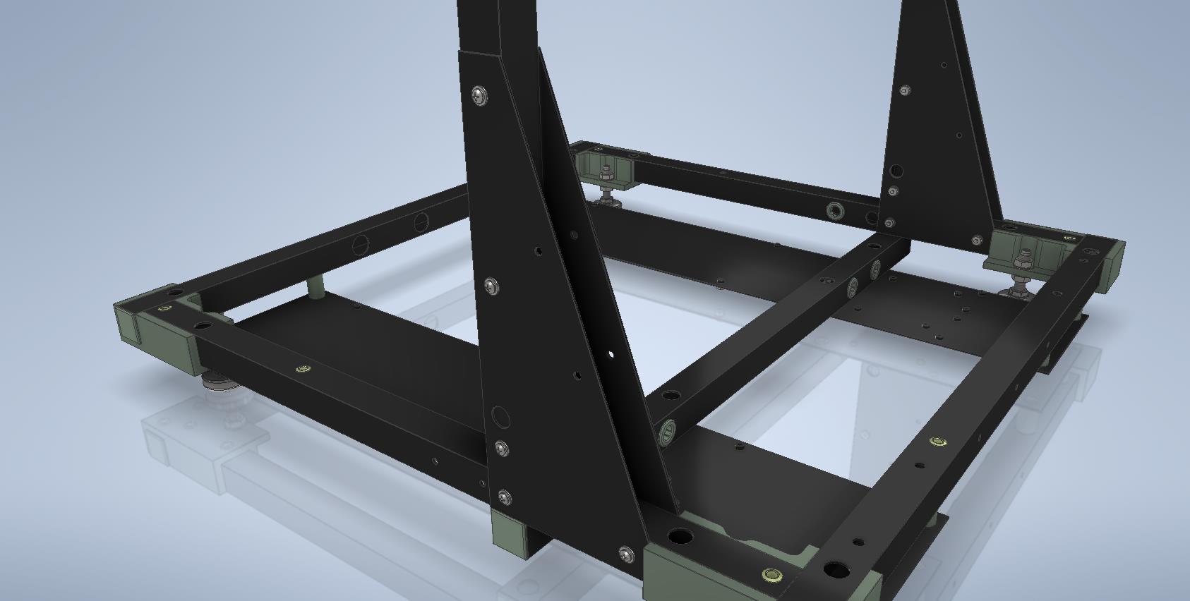
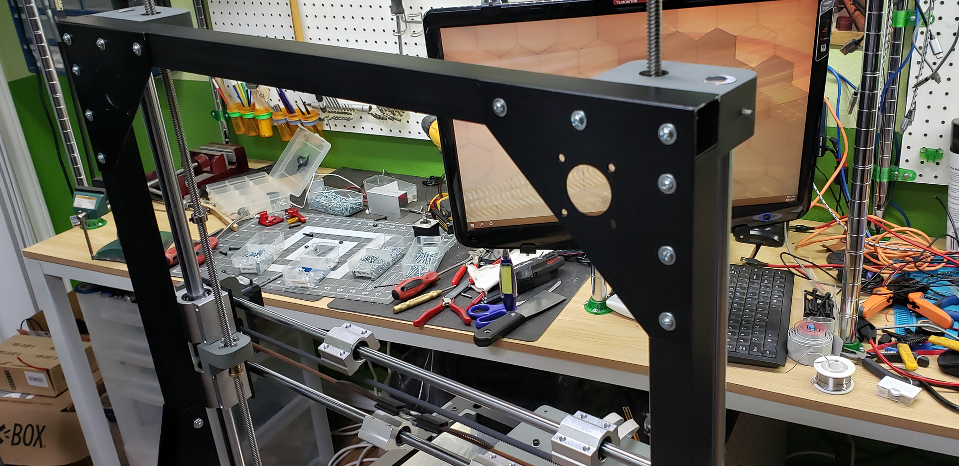
These parts of the frame can be considered directly related to the Z-axis:
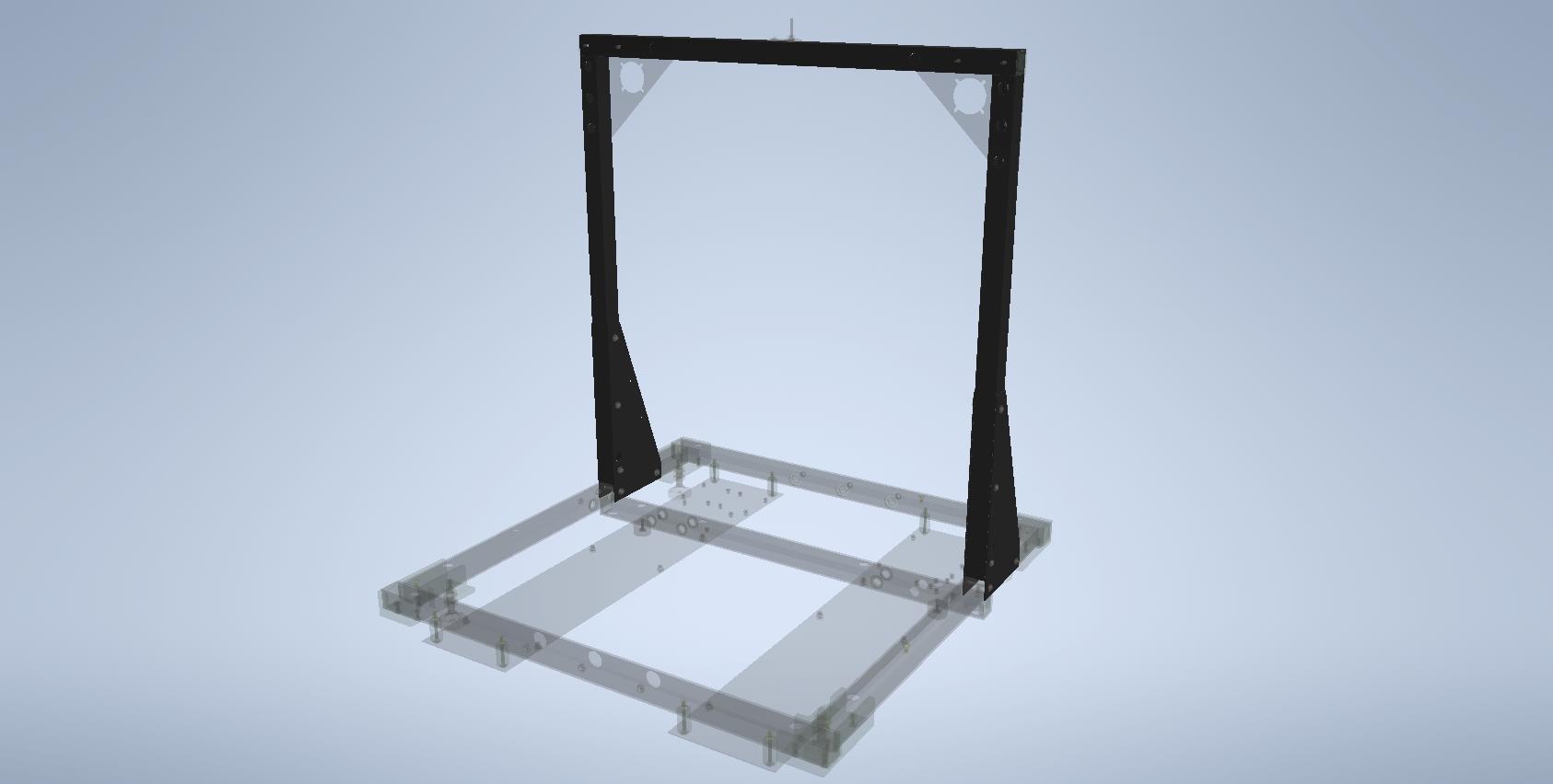
The “П” shape of this section of the frame was also made from sturdy 1×1-inch aluminum profiles with 1/16-inch wall thickness. They were carefully cut to size, drilled where needed, deburred, primed, and painted. This was the straightforward part of the adventure…
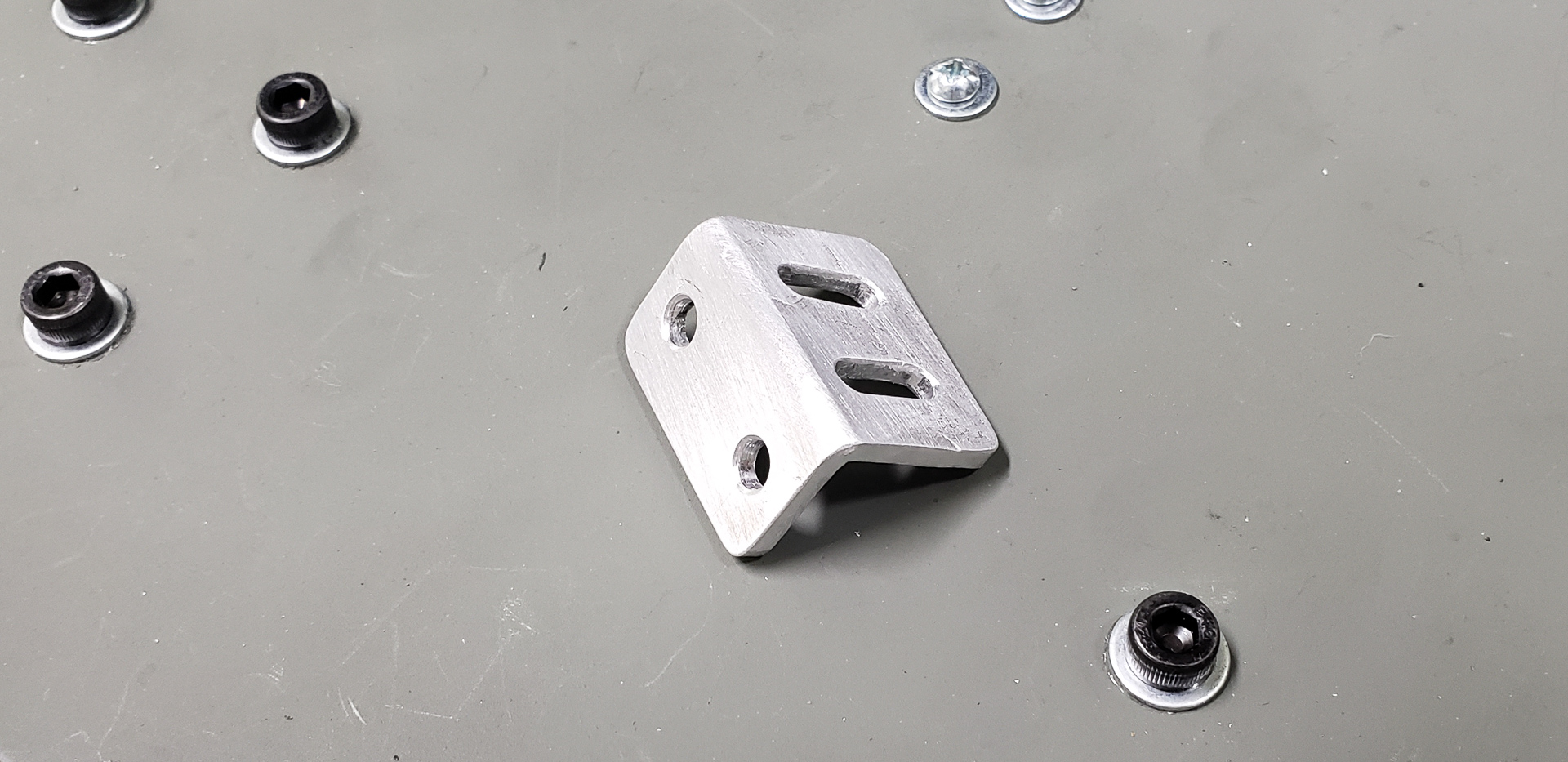
To attach the vertical posts to the base, it was decided to use wide triangular brackets. These would both ensure the proper angle and add rigidity.
Of course, I would’ve preferred to create this connection using machined blocks, just like the corner joints of the Y-axis frame. Unfortunately, finding “blocks” of that size that didn’t require selling a kidney was impossible.
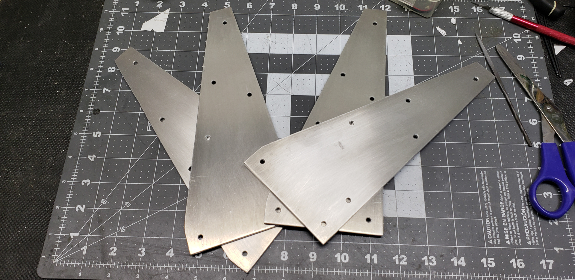
Four brackets were made, installed on both sides of each vertical post of the frame:
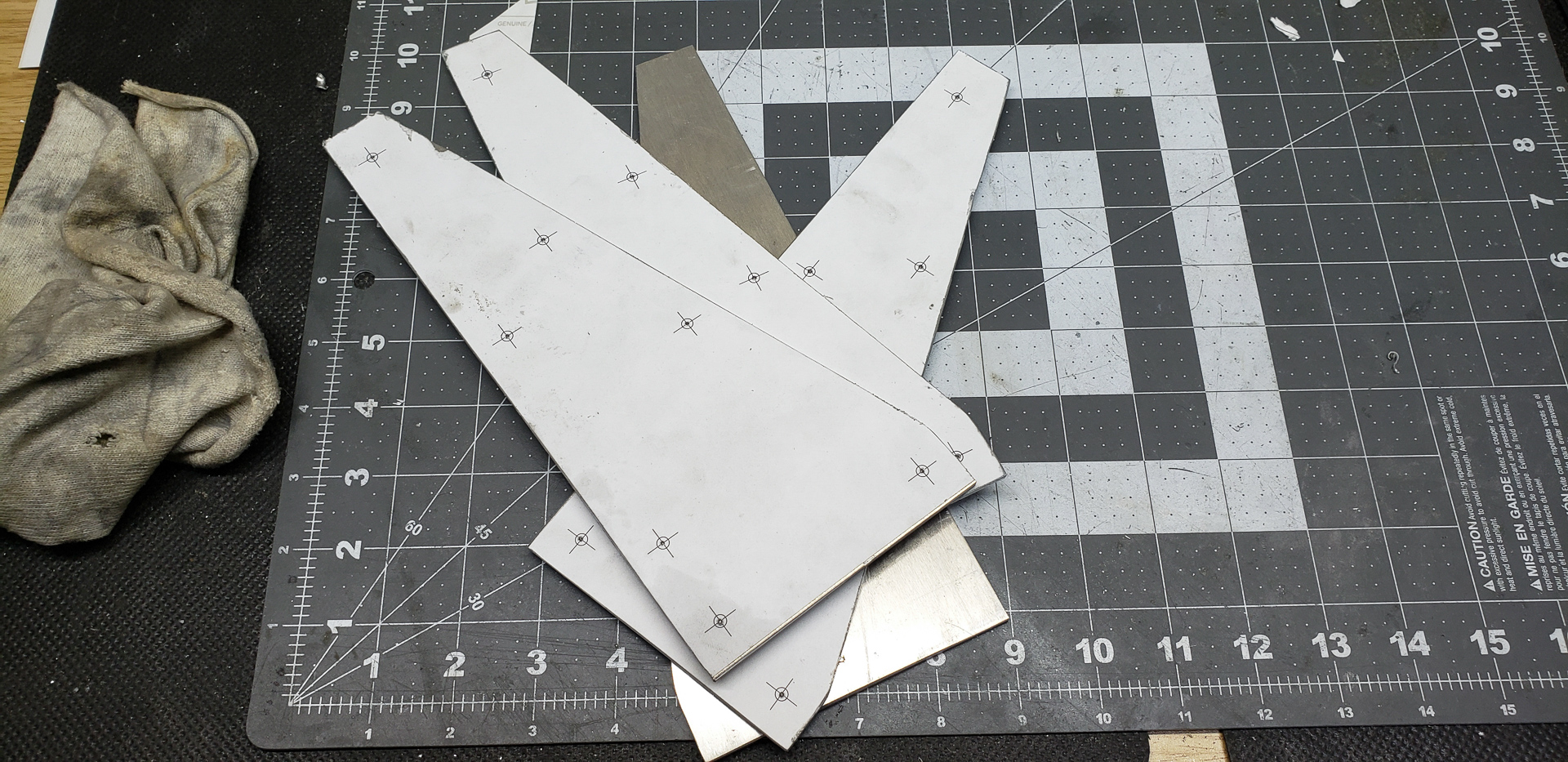
The brackets were cut from the same 1/8-inch aluminum as the base plate for the heated bed:
During assembly, before tightening all the bolts, each vertical post was aligned as precisely as possible at a right angle to the frame:
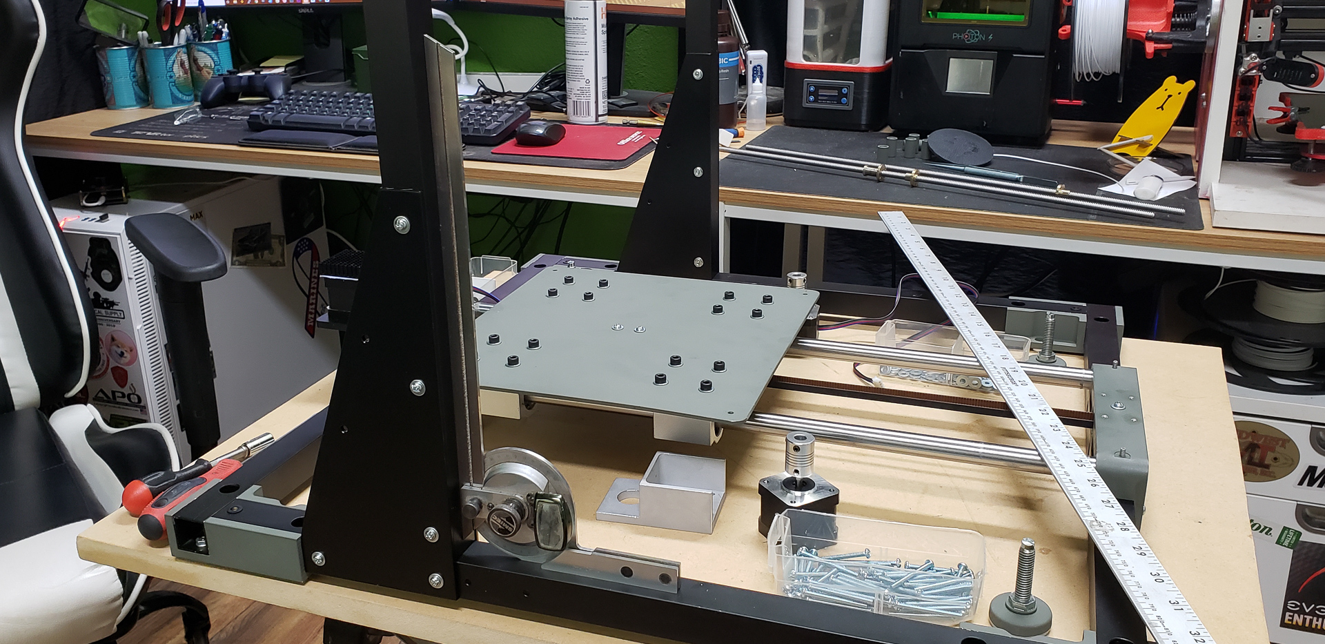
In reality, this still didn’t guarantee the desired result. The critical angle isn’t literally between the horizontal and vertical parts of the frame, but between the planes in which the Y-axis table and X-axis carriage move. It’s clear that the movement within these planes involves a ton of individual components. The cumulative errors that might arise during assembly are anyone’s guess. The best that could be done before everything was fully put together was to ensure maximum accuracy and care for every component and hope for the best.
As with the Y-axis, the Z-axis can also be divided into two main components: the supporting frame and the primary motor-support assembly on which the X-axis moves.
Unfortunately, the supporting part of the Z-axis couldn’t be made as a monolithic block consisting of two guide rails unified by a single mounting piece, as was done for the Y-axis. This is because the Z-axis guide rails are spaced too far apart, making it highly impractical to combine them into one solid aluminum piece.
As a result, each guide rail is an individual assembly mounted to the printer’s main frame:
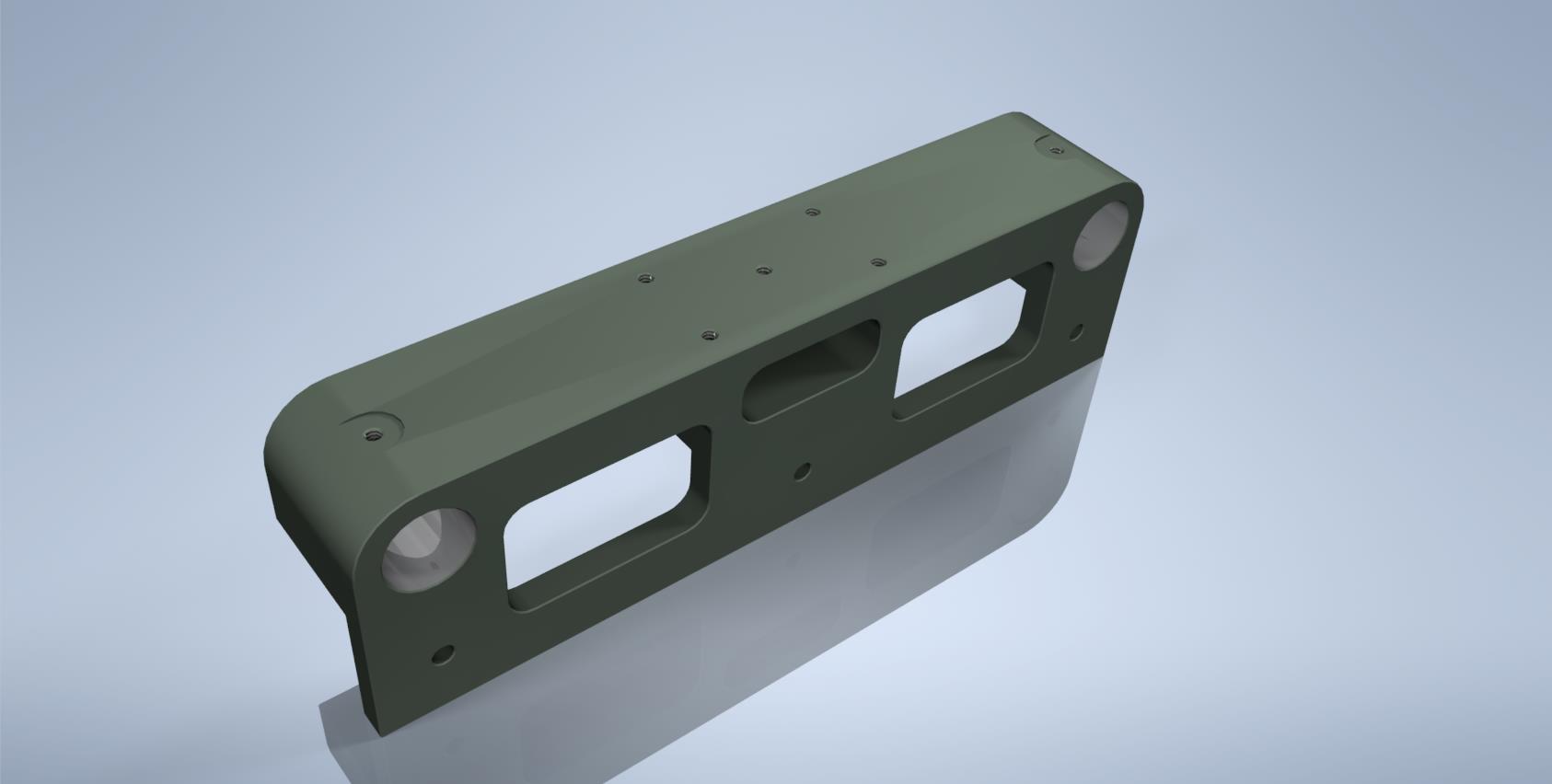
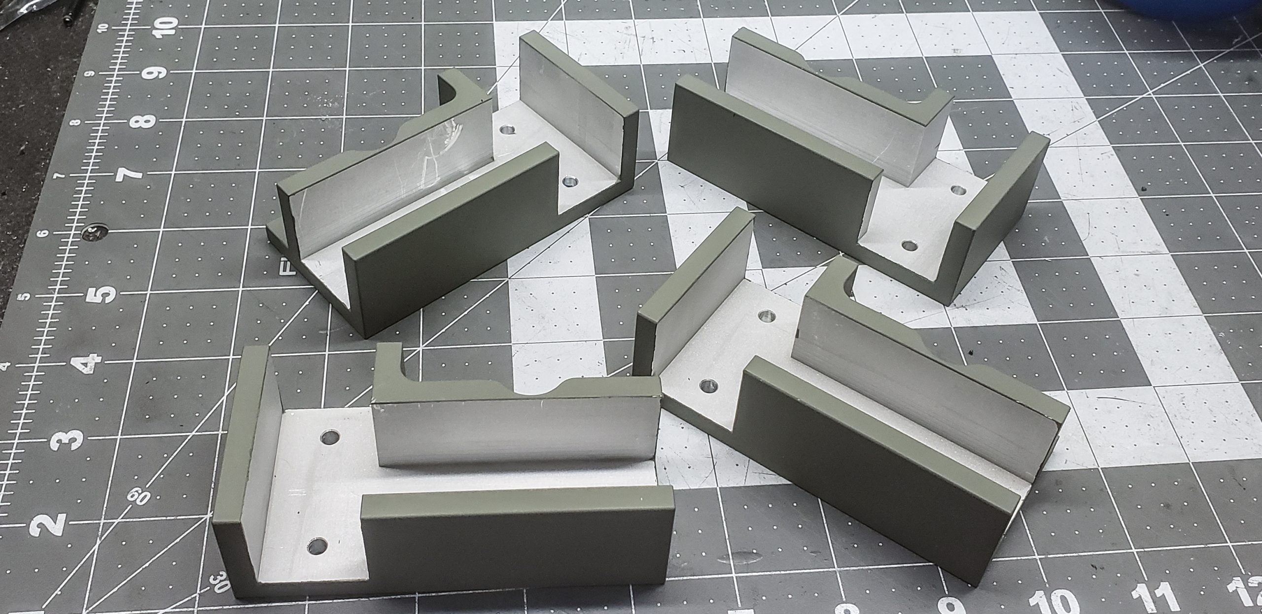
The most critical component here is the support block:

The key parameters of this block are the angles between all its planes and the diameter of the hole for the rail. In other words, every feature of this block is critical.
Once the blocks are mounted on the frame, the rails can, of course, be inserted into them temporarily, but only to ensure they don’t wobble in the holes and are perfectly parallel to the vertical posts of the frame. Before proceeding with their final installation, the structure needs to be supplemented with the “motor” section.
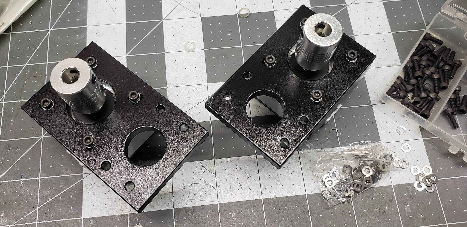
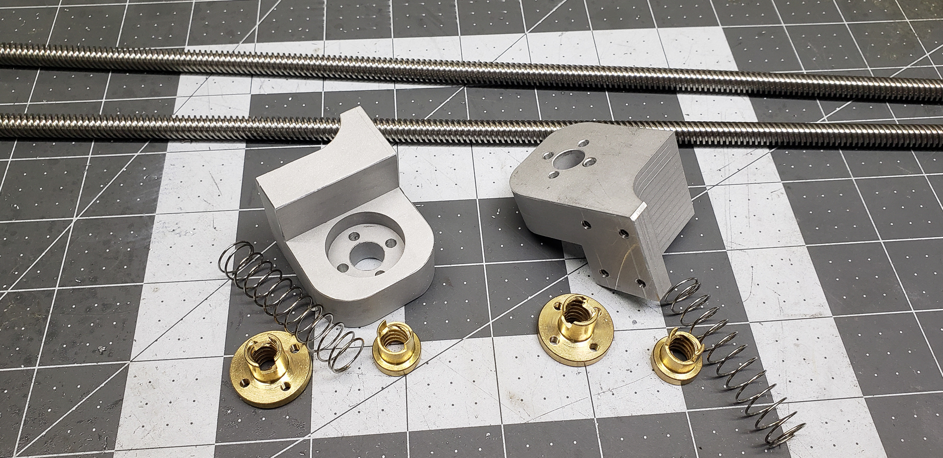
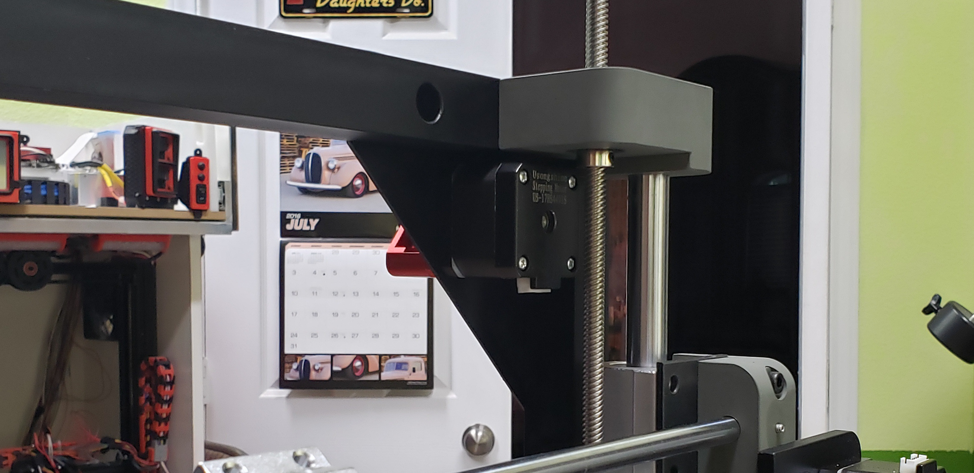
The “motor” section of the Z-axis consists of another set of support blocks, inside which the motors are mounted. These motors are connected to lead screws that will move the X-axis up and down:
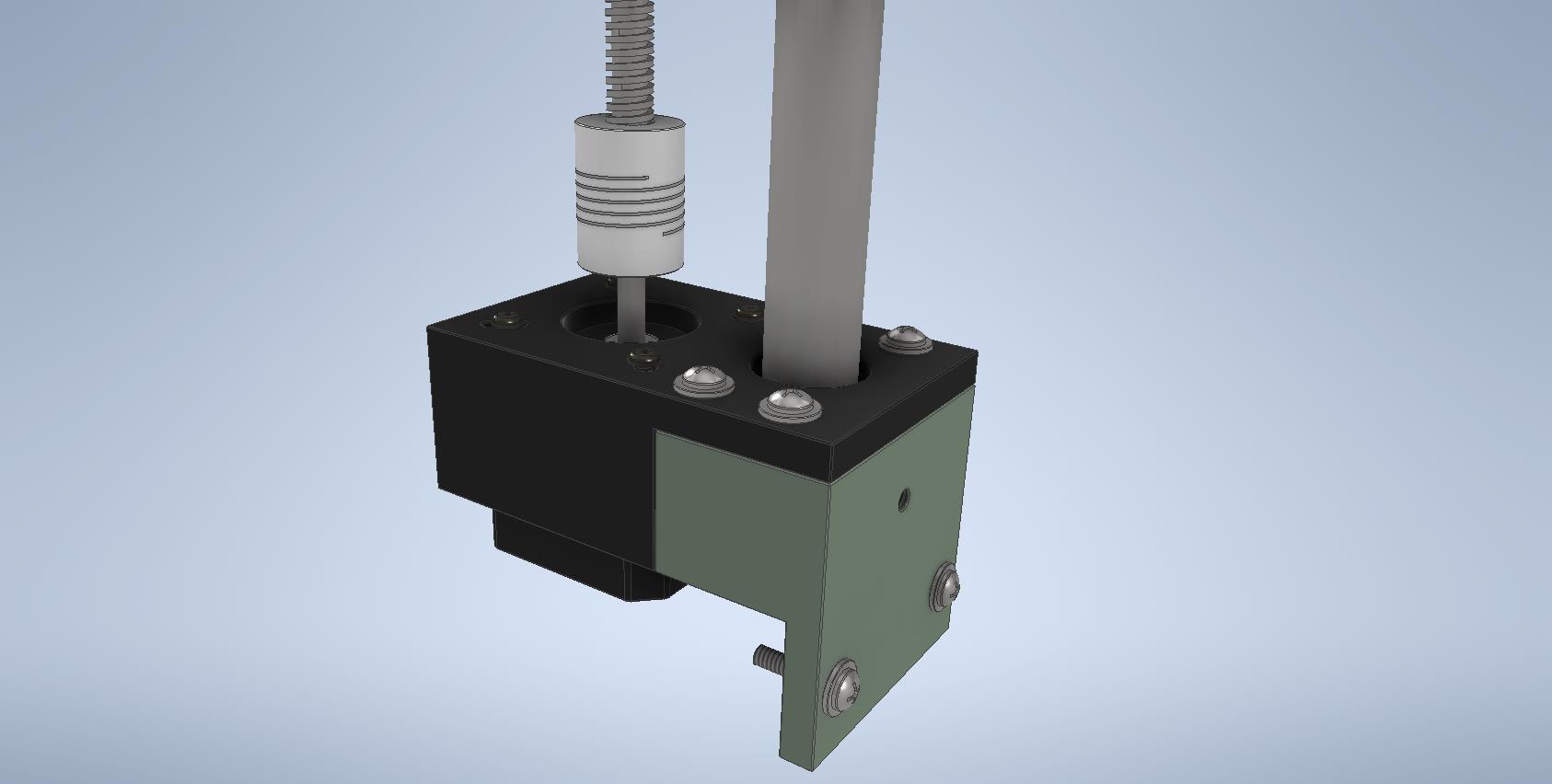
For the motors, a pair of these square “cups” were made:
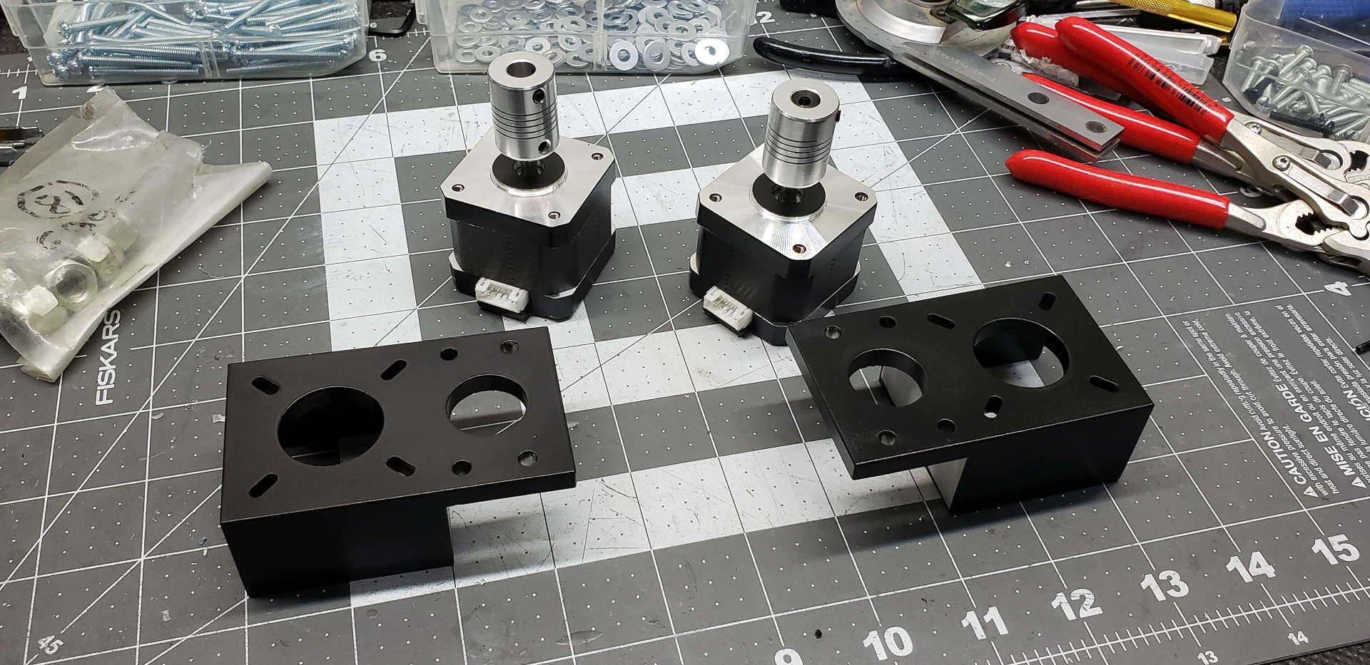
The key here is that a simple plate, even a thick one, might not be sufficient. The machine, to put it mildly, is quite heavy in every element. These motors, through their worm gears, will have to bear the weight of the entire X-axis bar — complete with all its bearings, guide rails, extruder nozzles, motor, fans, and other components.
In an ideal world of pink unicorns, the Z-axis motor block and the guide rail block would have been made as a single monolithic part. But in the harsh reality, I couldn’t find an aluminum “brick” of the required size. The best I could do was to create this combined structure using two smaller “bricks.” Alas…
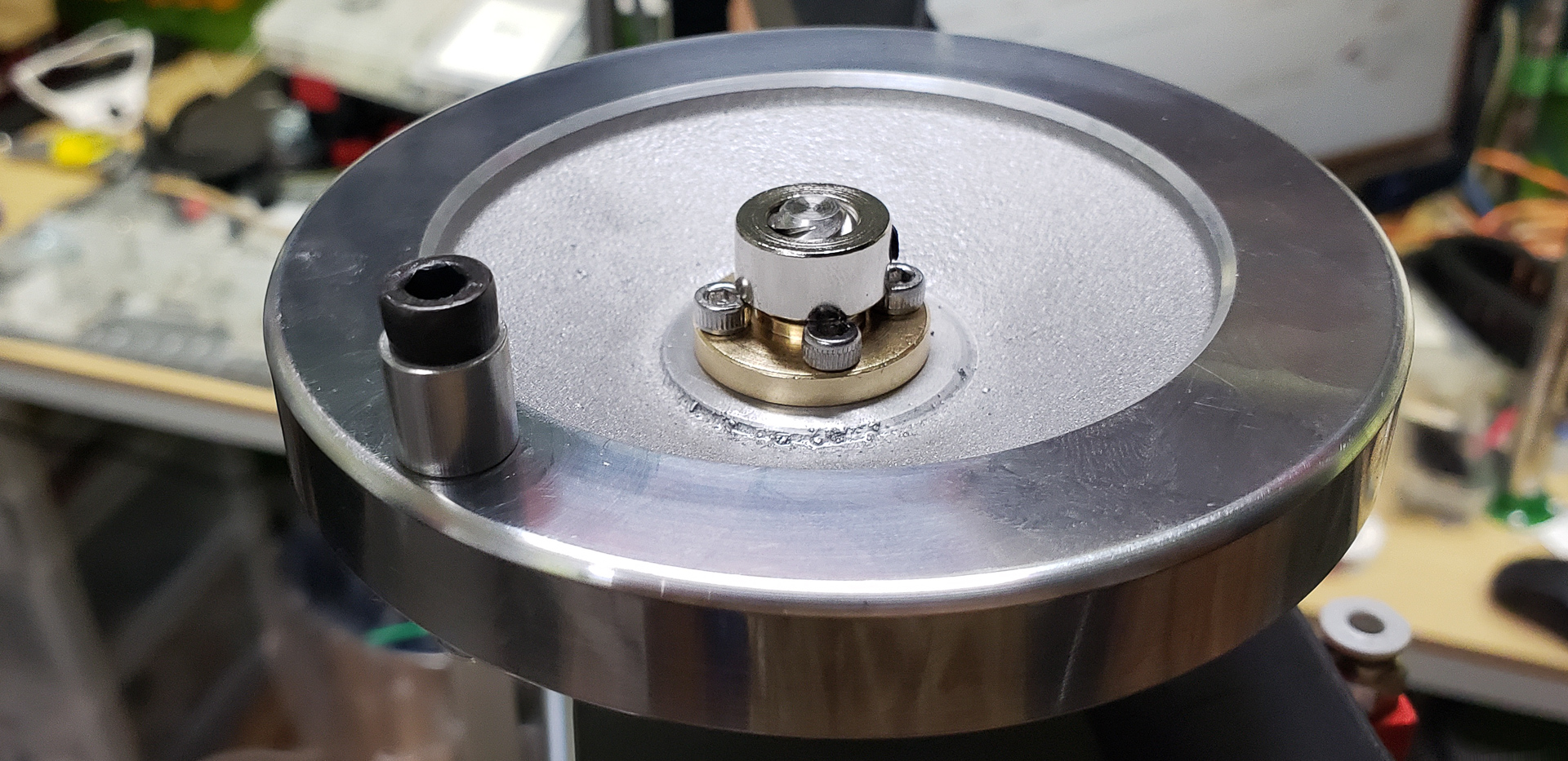
The adapters connecting the motor shafts to the lead screws are designed somewhat like universal joints:
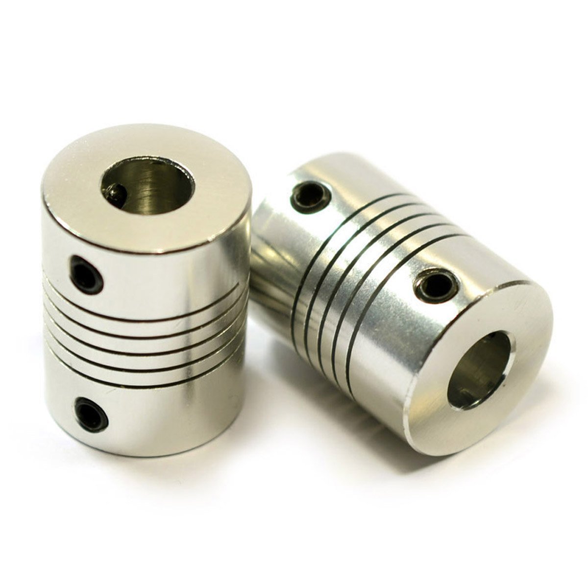
The issue is that humanity has yet to invent perfectly accurate robotic machines, ultra-durable carbide steel, precise measuring tools, or flawless quality control… All of these still await invention in an unimaginably distant future — probably after warp drives and anti-gravity.
For now, we’re doomed to receive lead screws bent like a bow or twisted like DNA spirals. Obviously, with such a setup, the nut assemblies sliding along the warped screws would constantly converge and diverge during motion. And since the rest of the structure is rigidly fixed, allowing no such wobbling, the inevitable outcome would be the entire system jamming solid.
The first set of two screws I received was promptly sent back to Amazon with a suggestion to shove them where the sun doesn’t shine for the factory worker who made them… Well, not really — I marked the return reason as “not as described” and gave the seller a single star. But my frustration at the time was off the charts. I had anticipated some issues, but… Their arc-like shape (visible to the naked eye!) was so bad they wouldn’t even roll off a plywood sheet tilted at 20–30 degrees! This was way beyond the boundaries of Good, Evil, Limbo, and the entire Universe. Amazon, Alibaba, anyone — this is unacceptable. Those screws haunted my nightmares for two nights straight…
After several tries, I finally managed to get a set of screws that were at least somewhat straight. They still have a slight tendency toward “curvature,” but nothing as catastrophic as the first set. This residual misalignment can be compensated for with these “universal joint” couplings. These allow smooth rotation transfer from the motor shaft to the lead screw, even when perfect alignment is not achieved.
For now, everything seems sturdy, reliable, and within expectations. However, it’s still too early to assemble the rails, bearings, and lead screws together.
The Z-axis as a whole can only exist and function in its completed form. You can’t just attach one block, test how it works, make adjustments, then attach the next block, and so on. It doesn’t work like that. Well, technically, the motors will spin, and the bearings will slide, but this tells you absolutely nothing about the Z-axis as a whole and is entirely useless for tuning. It’s an all-or-nothing kind of deal.
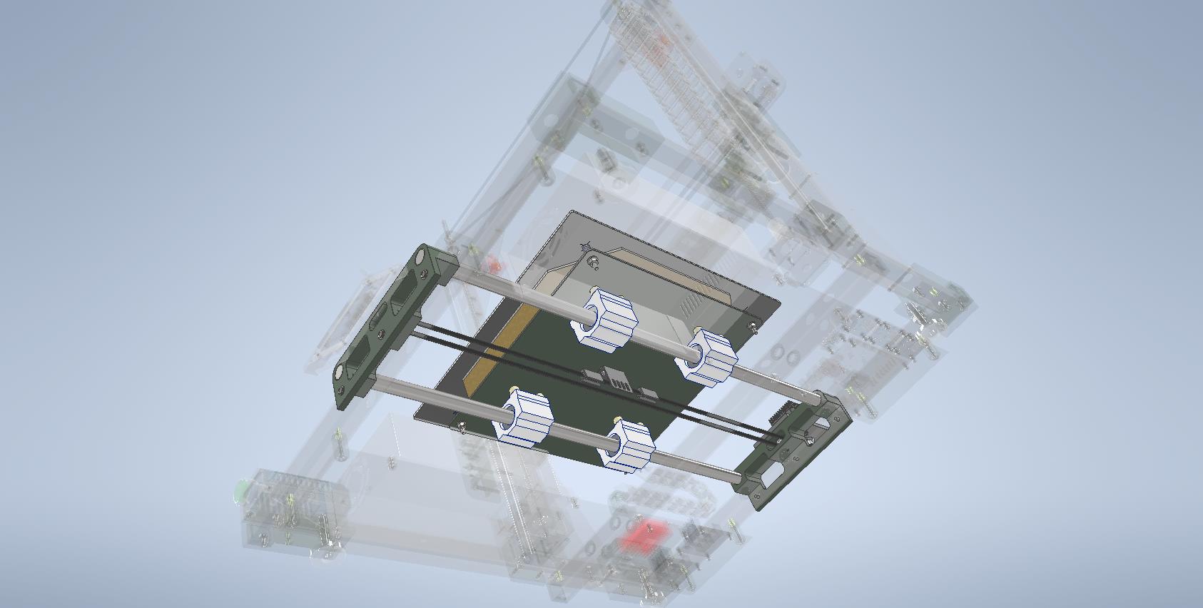
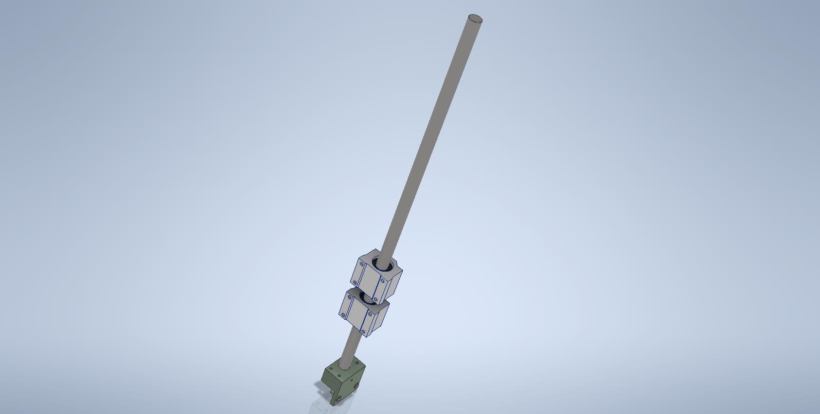
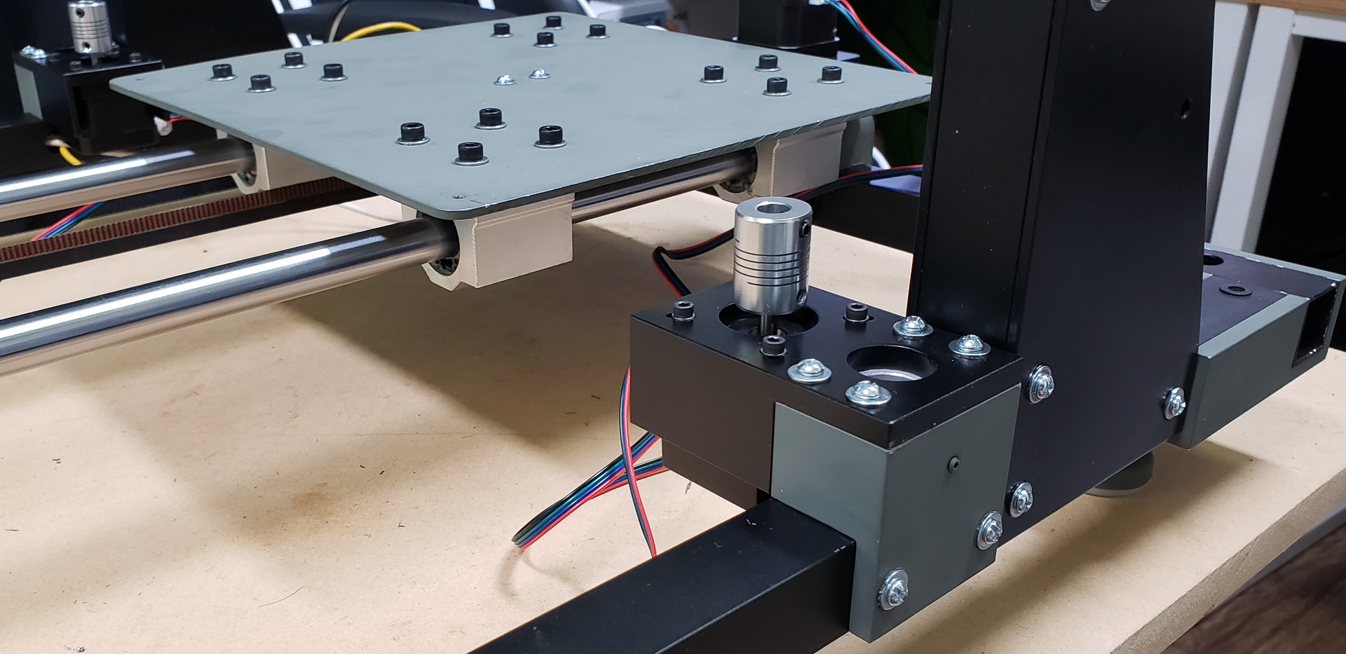
The next part of the structure includes the lead screw nuts, which will move the future X-axis up and down via the motors and lead screws (the green part between the sliding bearings):
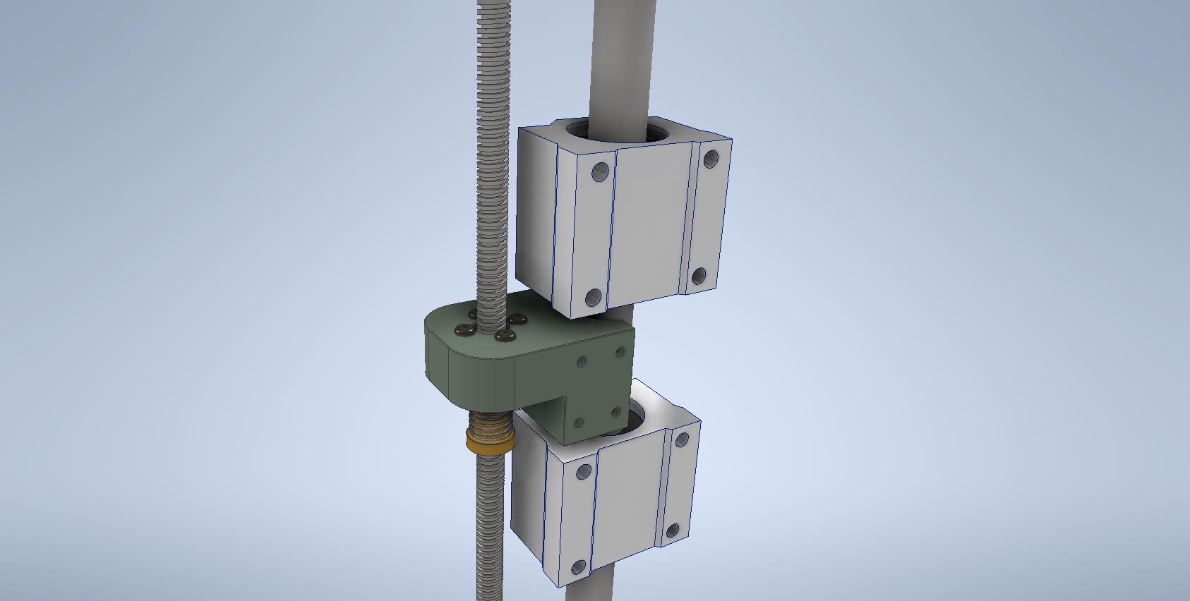
These nuts can’t simply be added later during the assembly of the X-axis. They must be mounted during the Z-axis assembly phase. So, while it might seem logical to classify the nuts as part of the X-axis due to their direct function, I’ve included them as part of the Z-axis because the Z-axis cannot be complete or tested without them:

As you can see, the nut isn’t just a threaded hole. This particular design is called an Anti-Backlash Nut. They come in various types and levels of complexity. In this case, the simplest version was used.
The principle of a worm gear, despite all its advantages, does come with some downsides (as does everything in this troubled, sublunary world). One of these downsides is the backlash in the nut’s movement along the lead screw. When the direction of movement changes, the lead screw spins for a moment without moving the nut, compensating for the backlash between itself and the nut’s thread. In Russian engineering terms, this is referred to as “dead travel.” In high-quality assemblies, this travel is typically very small. However, no matter how small it is, when dealing with precision in tenths of a millimeter, it becomes noticeable.
For example, let’s say you lower the X-axis by 1 mm. OK, it’s lowered. Now you want to raise it back by 1 mm. Before the lead screw starts lifting the X-axis, it compensates for the backlash between the screw and the nut. The controller has no idea how far anything has actually moved. All it knows is to make N steps with the motor to move something by 1 mm. That’s exactly what the controller does. It doesn’t care that a couple of those steps were wasted compensating for the backlash. As a result, the X-axis doesn’t move up by 1 mm but by, say, 0.99 mm.
At first glance, this seems like a negligible difference. But during printing, this error doesn’t always cancel out and can begin to accumulate in one direction or another, eventually becoming visible to the naked eye.
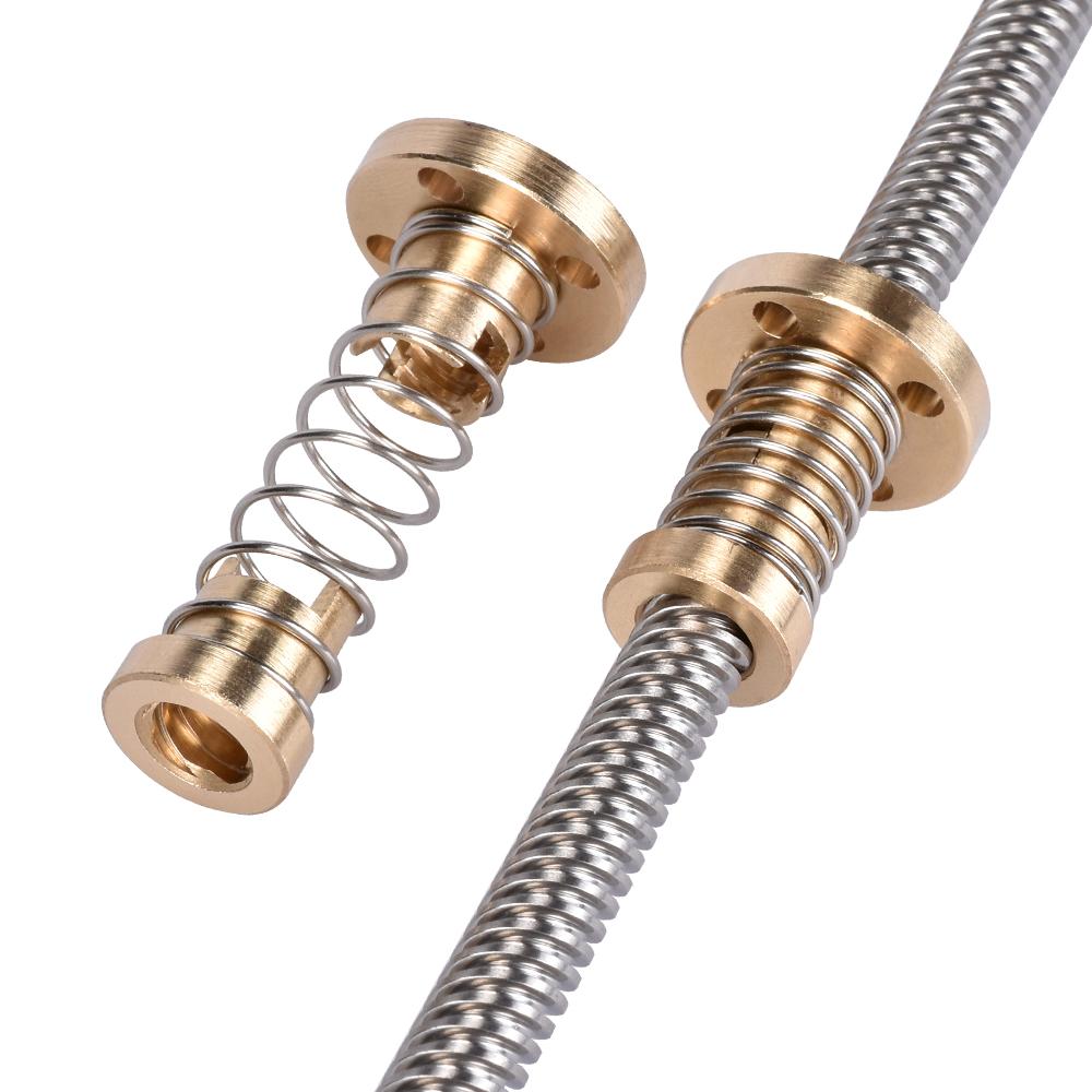
Spring-loaded nuts like these are designed to eliminate backlash in the transmission. If not completely (which, firstly, is impossible and, secondly, counterproductive — the entire mechanism would seize due to friction), then to reduce it to an insignificant level over extended periods of operation. Essentially, this design consists of two separate nuts, each pressed by a spring to opposite ends of the backlash range. Both nuts are linked together to rotate simultaneously. No matter which direction you pull one nut, the other follows, compensating for backlash by staying pressed against the opposite limit.
And so, it all looks something like this:
The irony is that, in this specific case, all this fuss about backlash is pure overengineering. The assembled X-axis is so heavy that Earth’s gravity alone takes care of eliminating the backlash. The X-axis is always pressed by its own weight against the lower limit of the backlash, whatever it may be. During printing, it’s simply impossible for any force to arise that could overcome the axis’s weight and push it towards the upper limit of the backlash.
Even after installing the nuts, the Z-axis assembly is still incomplete, and it’s too early to try moving it…
At this stage, I have a sturdy base for the rails and motors, as well as a reliable movable section to support the X-axis. However, there’s still nothing to prevent the entire structure from spreading apart at the top.
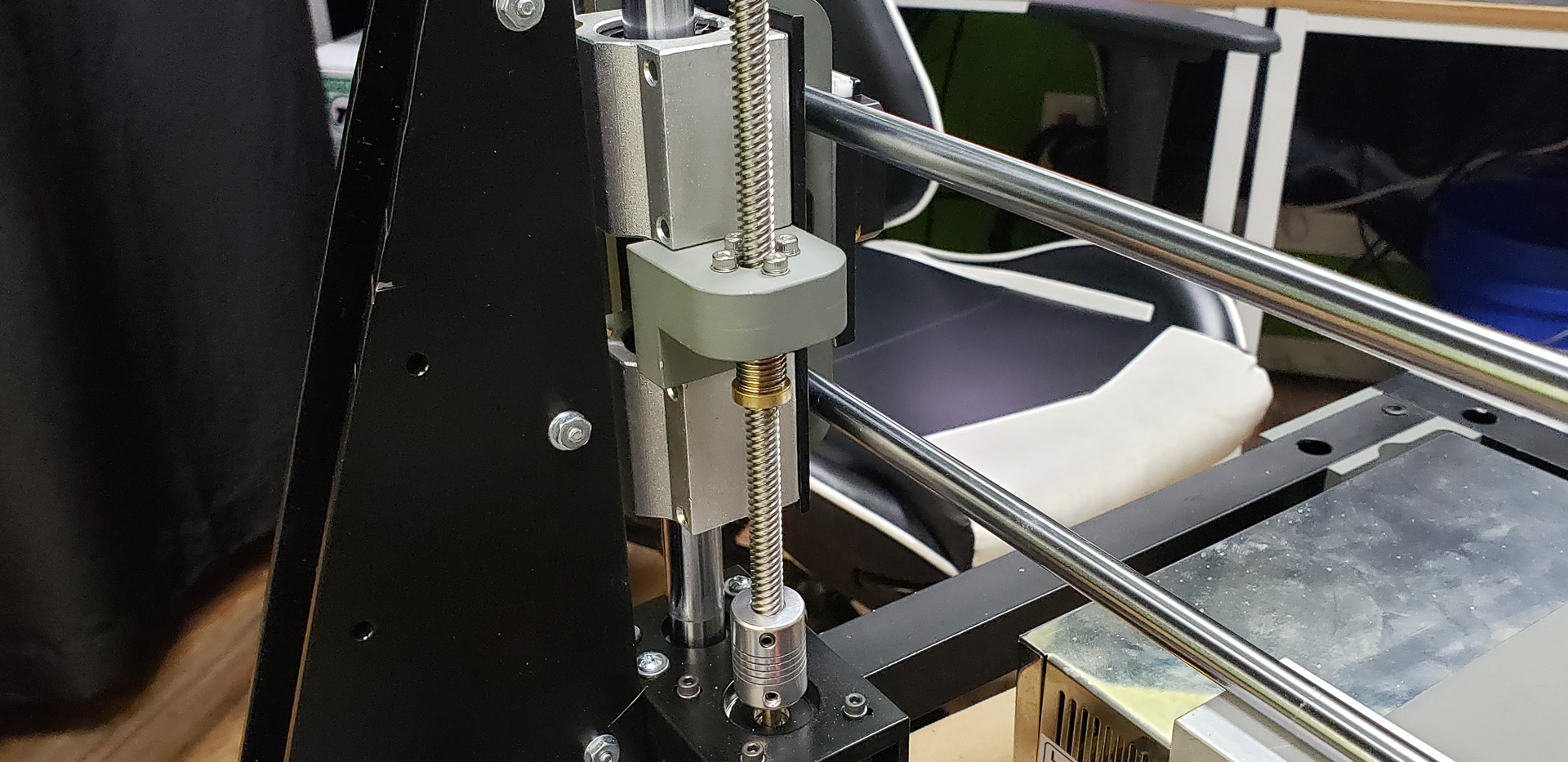
To secure the rails and lead screws at the top of the frame, the following blocks were designed:
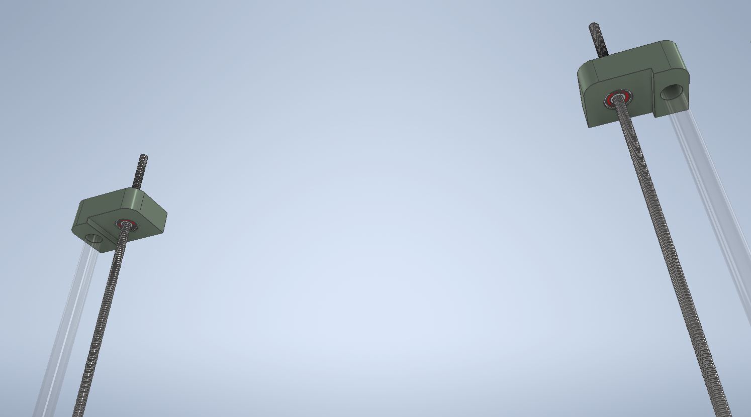
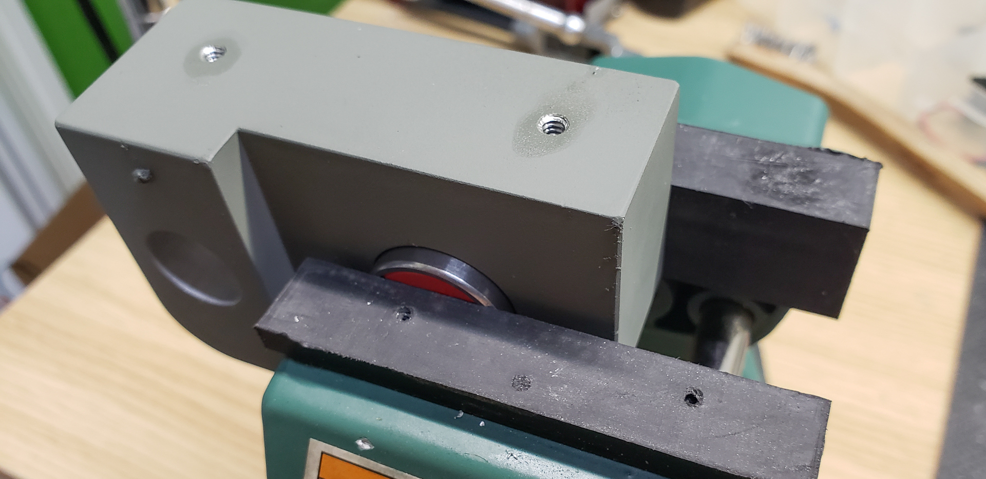
They are nearly identical to the lower support blocks but are less massive, made as a single piece, and include a bearing instead of a motor:
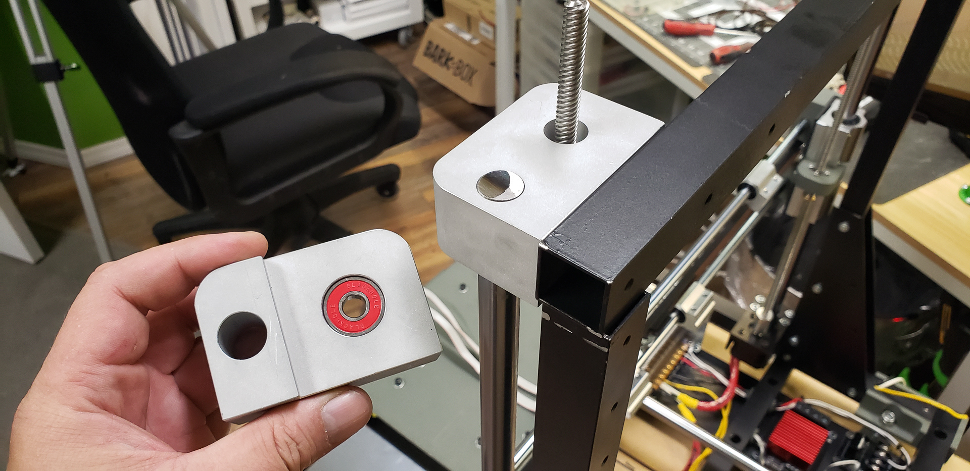
As you can see in the last photo, the corners of the frame at the top are also reinforced with corner brackets. These brackets not only strengthen the top section of the frame but also serve as mounting plates for the extruder motors.
The printer, as mentioned at the very beginning, is being built with two print heads. Accordingly, it requires two extruders to feed the filament.
These extruders were mounted on the corner brackets reinforcing the top section of the frame:
From here, the filament will be fed through tubes directly to the print heads on the X-axis.
With this, the Z-axis is essentially complete. It now contains all the necessary elements and is fully ready for operation.
No build is complete without the cherry on top.
Here’s the thing… On the late Black Widow, the Z-axis was driven by just one motor. Both lead screws were synchronized via a single belt. If I needed to manually raise or lower the printer head without electronics, I’d simply pull the belt one way or the other by hand. It wasn’t exactly convenient, but the Widow’s design didn’t offer any other options.
On the Turret, I faced the same issue, but in a much worse form. Each lead screw is connected only to its own motor. Electrically, they are synchronized — no issues there, they work perfectly in tandem. But if I need to move the head by hand, it’s a disaster. No amount of human coordination will allow you to turn two independent lead screws in perfect sync by hand. The slightest desynchronization causes the X-axis to tilt and lose its calibration.
There were two options: either forget about manual Z-axis control entirely or add a synchronizing belt. In the latter case, it would be a feature solely for the human operator. It’s completely unnecessary for the actual Z-axis mechanics.
The first option wouldn’t have been catastrophic. Situations where you need to move the printer manually during operation are rare. It’s always easier to press a button in the interface and let the machine move itself as needed.
However, at this stage, we’re dealing with an unfinished machine. Not only is there no interface, but the controller is just mounted in place and hasn’t even been connected to the power supply yet. And manual adjustments are happening constantly. Recalibrating the X-axis leveling every time I have to move it manually was becoming an unbearable chore.
So, I had to add the synchronizing belt:
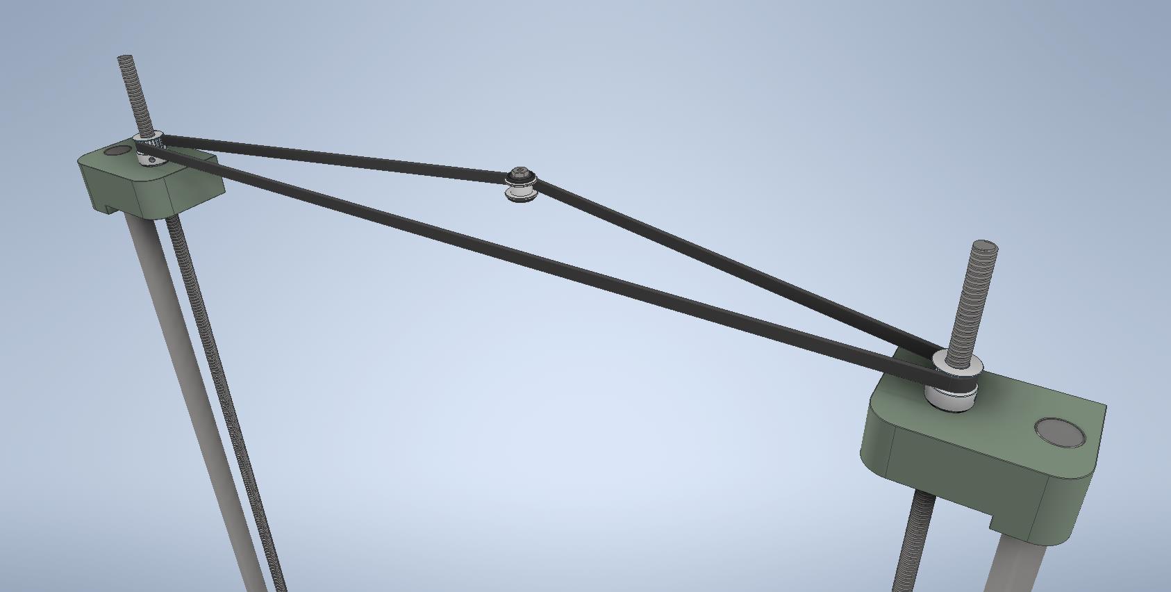
I naively believed it would be a temporary feature, only needed during the printer’s assembly:
As is often the case, anything “temporary” eventually becomes permanent. That belt is still there today, even though the printer can move its parts on its own without the intervention of the “meat sack.”
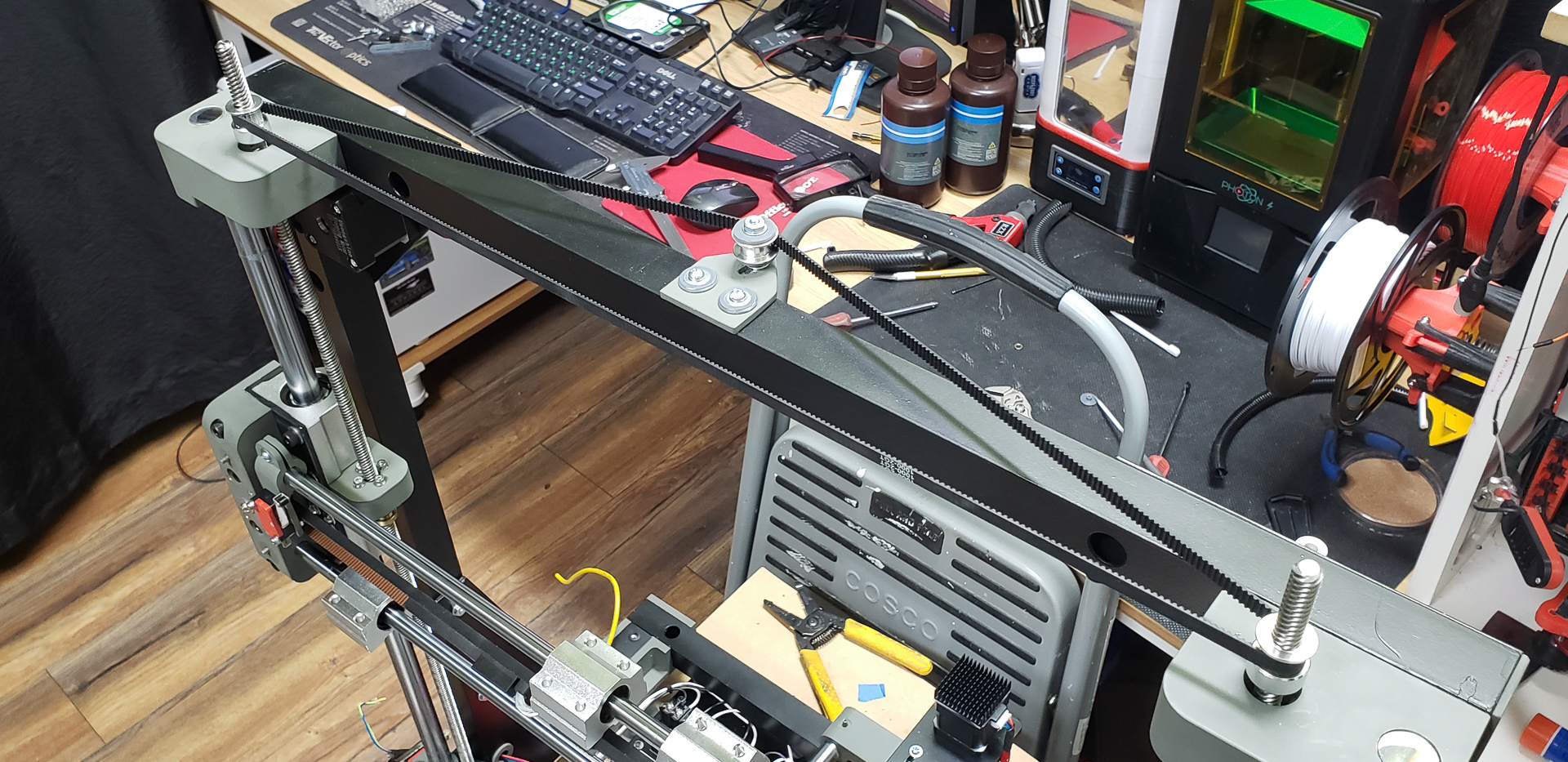
What’s more, this madness even acquired a ridiculously charismatic handle:
One of my colleagues gave me this handle as a gift years ago. His workshop was always full of random odds and ends. Occasionally, he’d sort through them and give away the less valuable items “to a good home.” That’s how I ended up with this crank. It sat in my stash for about three years until its moment of glory finally arrived:
Now I can’t bring myself to get rid of this element, whether it’s strictly needed or not. Together with the handle, it has become part of the printer’s aesthetic. After all, a turret needs a handle to rotate, doesn’t it? On the one hand, a turret without a handle is exactly the same as one with a handle — just without the handle. On the other hand, a turret without a handle isn’t really a turret at all. So, both the synchronizing belt and the handle became a permanent part of the printer:
Plus, the handle isn’t entirely useless beyond manual control. On rare occasions, a motor might skip a step — perhaps something gets stuck, the driver overheats and glitches, or there’s a firmware bug. It happens. In such a situation, even if one motor skips a step, the synchronizing belt forces the other motor to skip the same step. The print will still be disrupted, but at least I won’t have to recalibrate the X-axis level after such an incident. So, there’s that…
In conclusion, the Z-axis is complete! Time to move on to the X-axis.
X-axis
The X-axis of the printer turned out to be both the most complex and the simplest part of the build. Complex, because it includes the print head. Simple, because it was built last.
By the time it was constructed, all the other axes were already complete, the printer was even executing some rudimentary movements, and it was 100% clear that everything was going according to plan. It’s likely this will be the shortest section in the entire series of articles about the printer.
Unlike the other axes, the X-axis has no associated part of the printer’s main frame. It stands entirely on its own:

This made it all the more important to get everything right. Any misalignment here can’t be adjusted or corrected later.
While building the Y-axis, I became convinced that the combination and shape of parts chosen for it were exceptionally successful in terms of structural rigidity. I wasn’t exaggerating when I said that the Y-axis could essentially hold itself together without the frame. For the X-axis, there’s no other choice but to support itself. So, it was built exactly according to the same principles as the Y-axis.
With one small exception. Since the X-axis uses 10 mm guide rails instead of 16 mm like the other axes, all the mounting components had to be scaled down by one and a half times. But that’s it.
Here’s the entire set of mounting and support components for the X-axis:
The rails fit perfectly into the designated holes. Equally perfect was the way the entire assembly mounted onto the designated lead screw nuts of the Z-axis:
The motor mount was designed and built in precisely the same way as before:
The tensioning pulleys follow the exact same design as well:
And the carriage driver, which the belts attach to, is unchanged (except for being one and a half times smaller, like everything else on the X-axis):
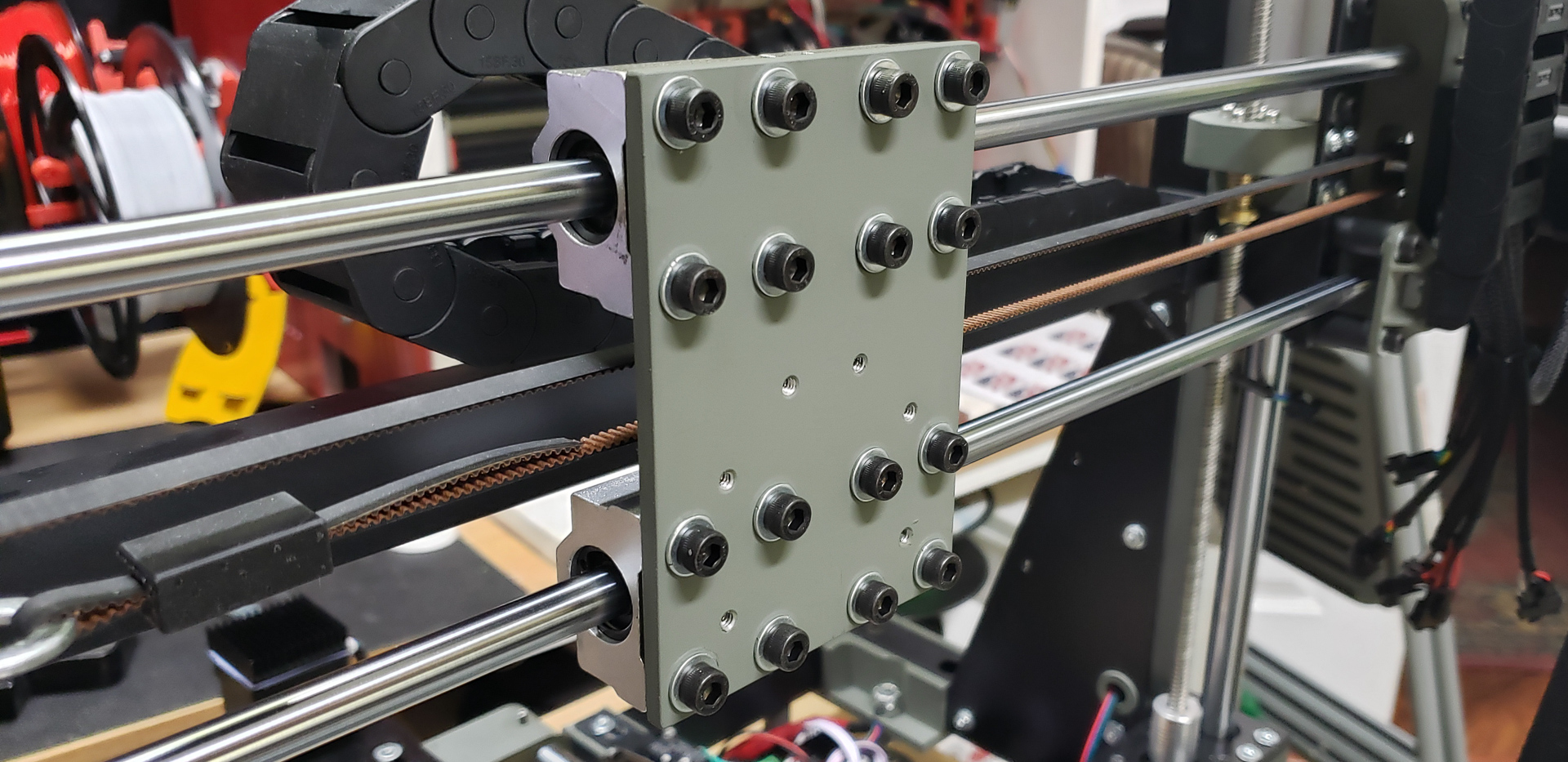
The mounting plate for the print head assembly is much smaller than the one that holds the bed. But it doesn’t need to support a bed:
Honestly, I don’t even know why I’m writing this part of the series. You could just scroll back to the article about the Y-axis and read it again… Yeah…
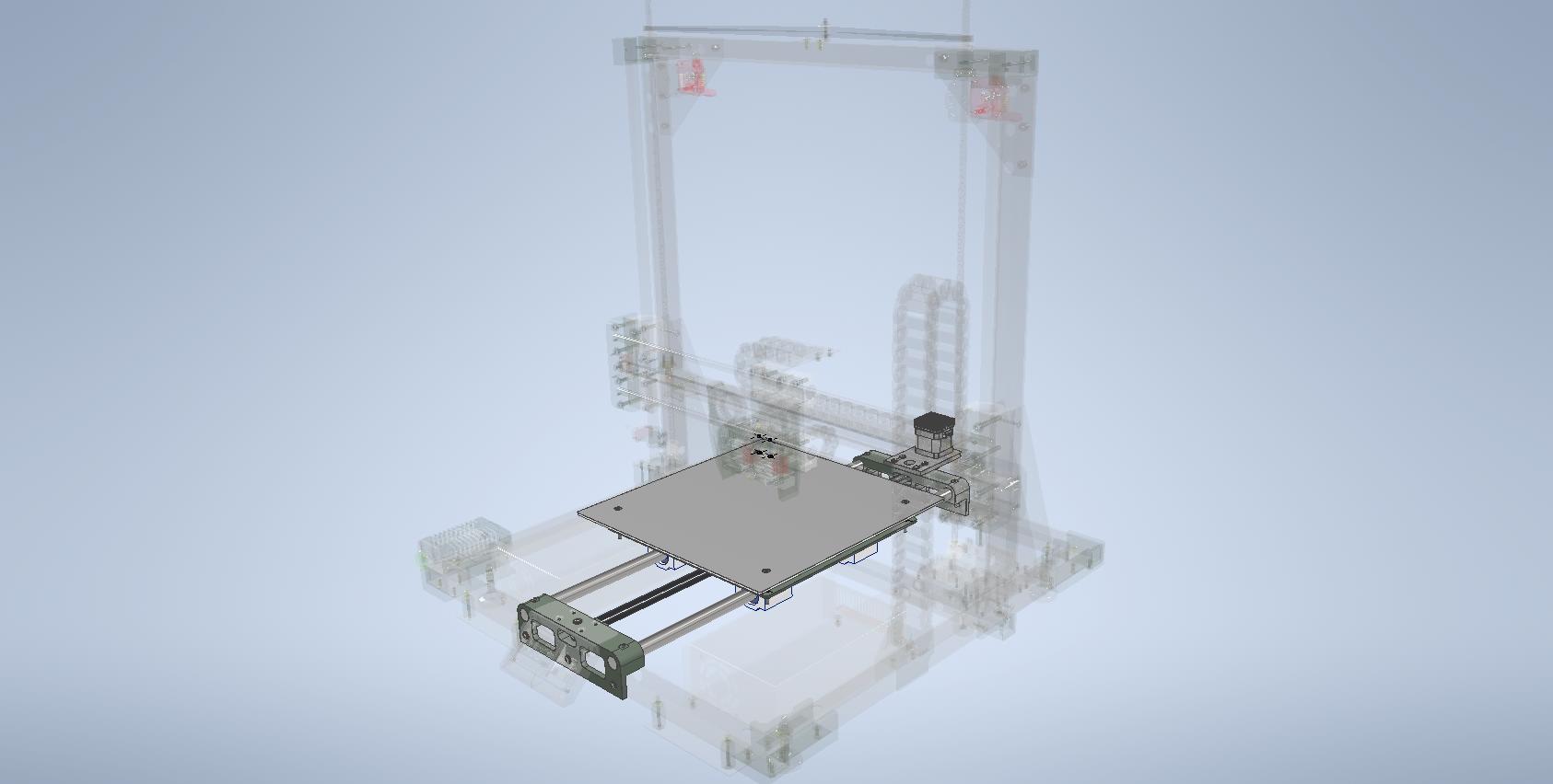
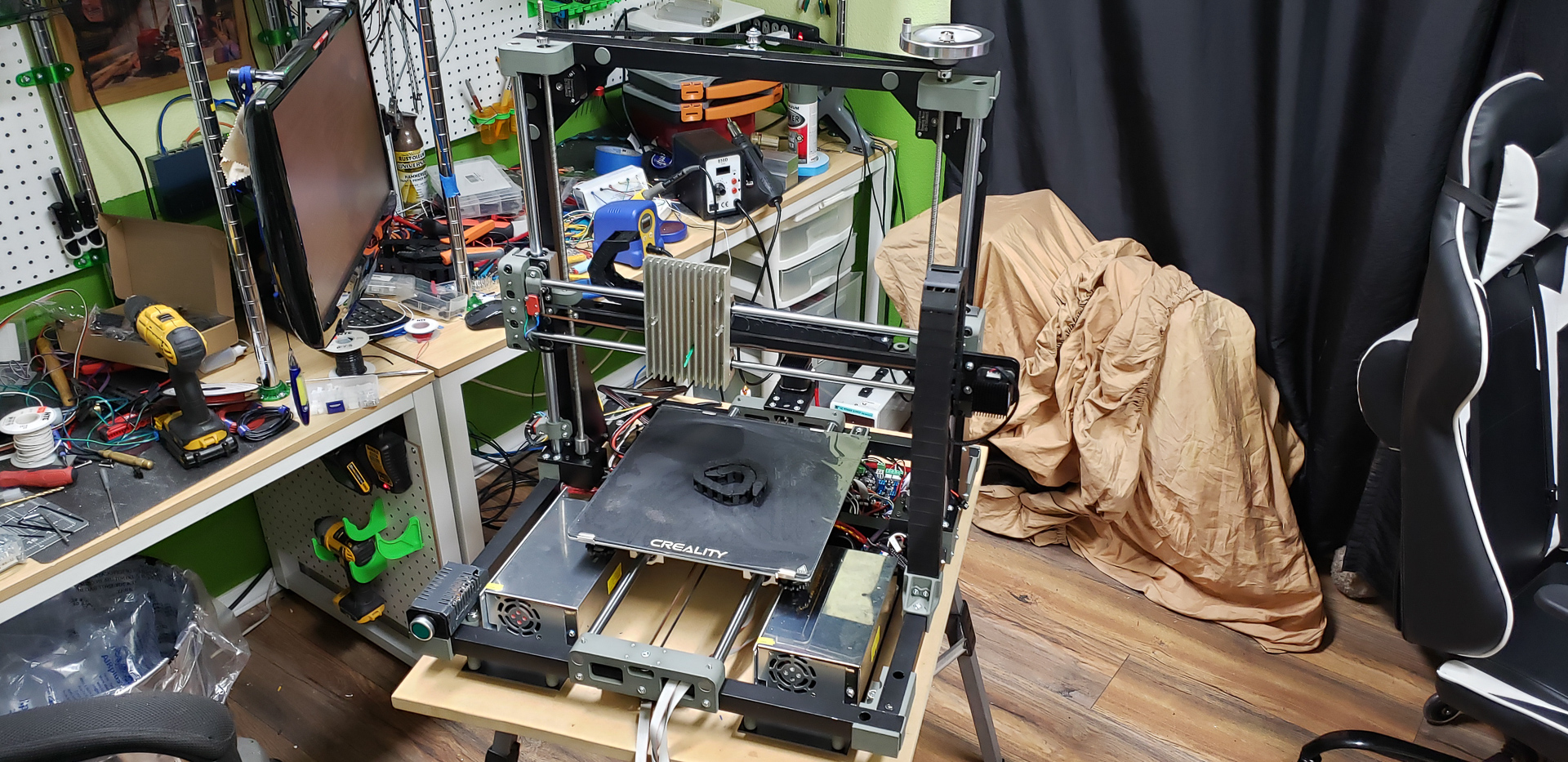
Finally, all the axes of the printer have taken their more-or-less finished form:
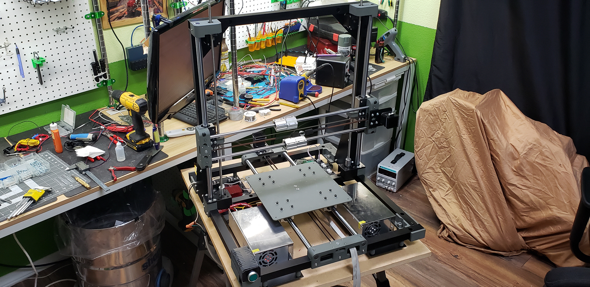
Guess what’s standing against the wall in the photo, covered with a sheet? That’s right! The mechanical dog, for which this entire printer was built. It’s covered because of the Cat… That little beast already got into the wiring in the dog’s head and chewed something up. I still don’t know what or how bad it is. I just found a few wires on the floor and identified them by their markings as coming from the dog’s head. What else that brainless creature has destroyed, I haven’t figured out yet… I really need to finish the printer faster to start printing the dog’s body panels, which will shield its delicate wiring. And I think I’ll need to embed an electric shocker in its nose to make sure someone learns to stay away!
At this point, I could probably end the story about the X-axis, but there is something unique about it: this bar behind the moving assembly:
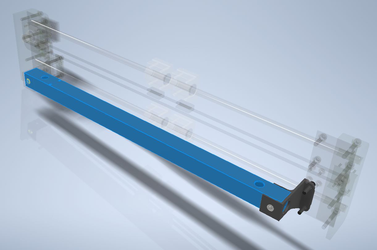
It’s a 1×1-inch aluminum profile, just like all other similar structural parts. However, it doesn’t serve as a load-bearing component or part of the main frame. Its sole purpose is to support the cables.
There will be a separate section in this series dedicated to the printer’s electronics, and there will definitely be plenty to discuss! For now, I’ll simply note that all the wires running from the controller to the print head are routed through several flexible conduits, like these:
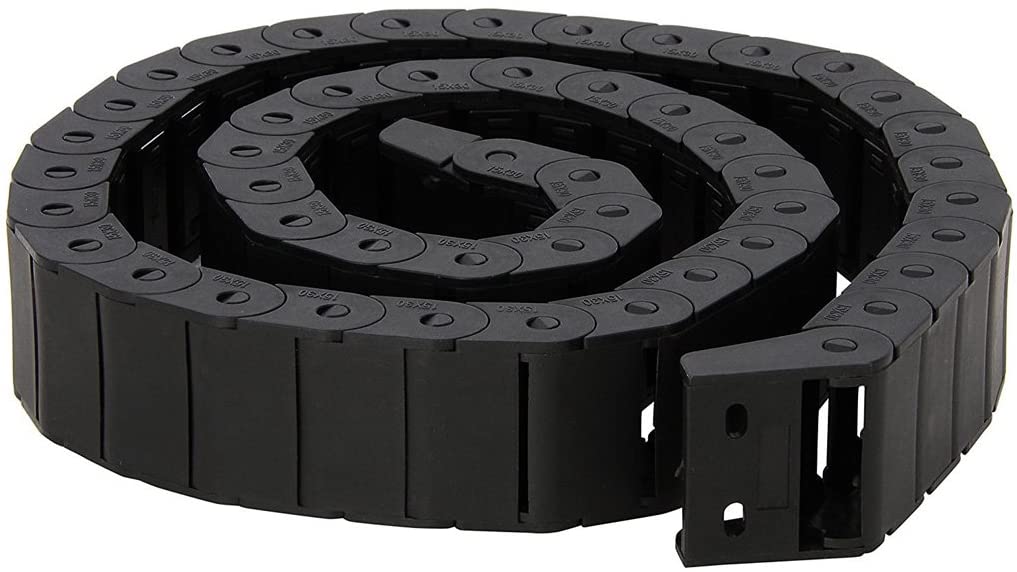
Typically, such conduits hold themselves well along their length. However, they need something to anchor their ends to and, where possible, a bit of support to prevent sagging. After all, it’s just plastic.
That’s where the aluminum bar behind the X-axis comes into play — it acts as an anchor and support for the conduit to prevent it from drooping:

Additionally, only the wires for the print head, which moves back and forth along the X-axis, are routed through this conduit. There are also some stationary wires in that area, such as those for the limit switch or camera. It’s most convenient to run these wires directly inside the support bar, where they’ll be safe and won’t snag on anything during movement.
After assembling and running a test of all the axes, the moment of truth arrived. Only now could I determine how accurate I had been in fabricating and assembling all the components of the motion system. The most critical and telling measure of this is the Y-Z angle between the print head carriage plate and the mounting plate for the bed (not the bed itself — it’s adjustable, so testing against it is pointless):
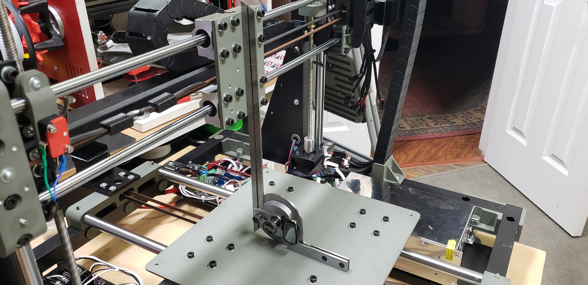
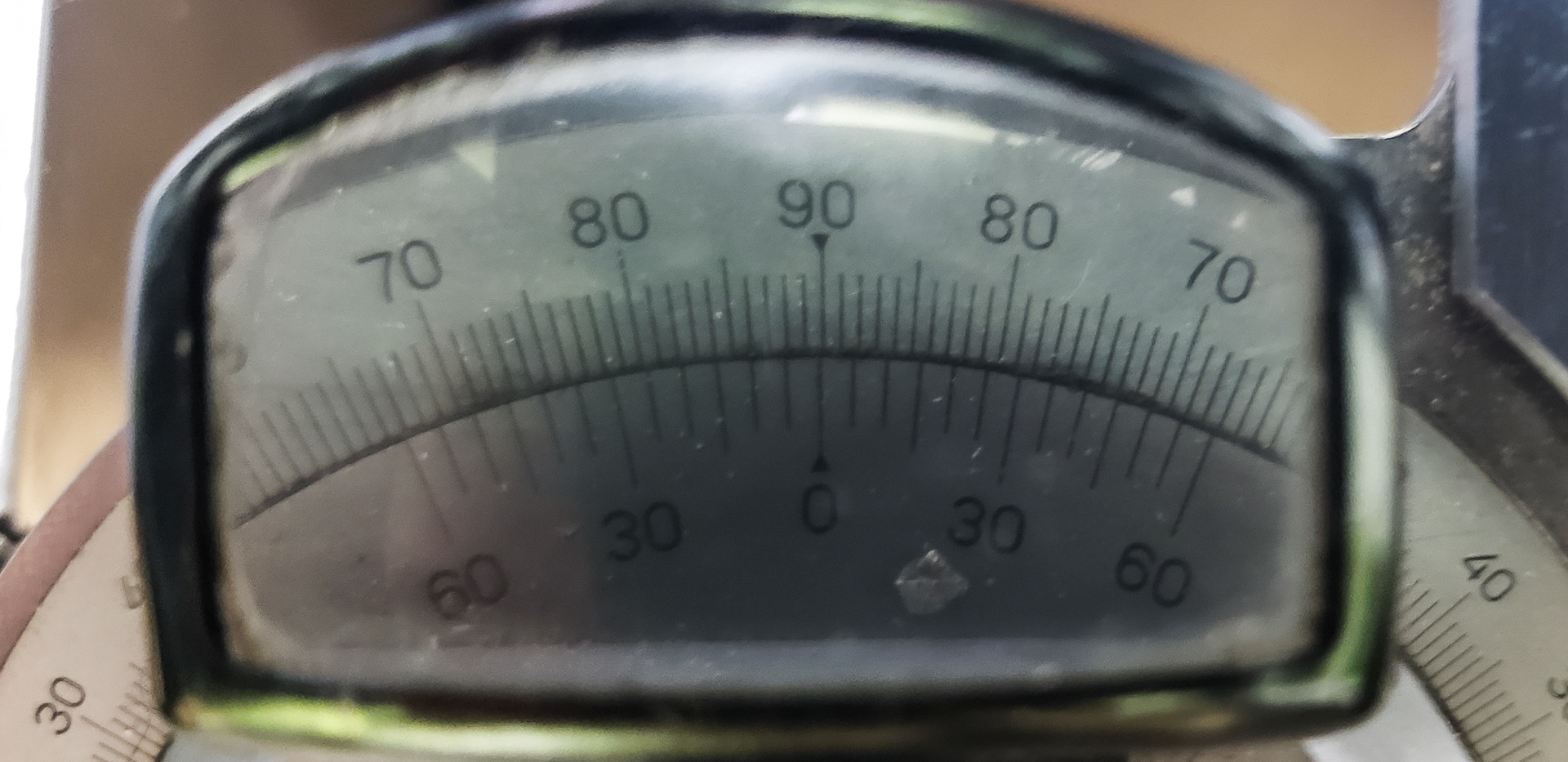
A deviation of minus one-tenth of a degree (-0.1°) seems like a victory to me in this case! Honestly, this deviation could very well be due to room temperature fluctuations or even the margin of error of the angle gauge itself (which, while good, is far from perfect).
The Y-Z angle is particularly important because it’s the most indicative. If it’s accurate, then everything else is likely fine.
This is simply because it’s the one angle in the structure that is almost impossible to adjust afterward. It’s determined as-is during the assembly of all the motion components. For instance, the X-Z angle can be adjusted by raising or lowering the arms of the X-axis on the lead screws at the sides. That’s simple — just set it correctly before synchronizing the motors, and you’re good. Fine-tuning can be done later if needed. The X-Y angle can also be adjusted by moving the vertical frame posts forward or backward. In my case, this wasn’t necessary because it naturally aligned quite accurately (and the X-Y angle is generally the easiest to adjust and the least critical for printing). The Y-Z angle, however, is influenced by almost everything — both the parts I fabricated and the ones I purchased. For example, the bearing housings: all eight of them, on both the Z-axis and X-axis, directly impact the overall alignment of the system. The same goes for all six guide rails.
In the end, I was pleasantly surprised by the results and, after this outcome, had no further doubts about the project’s successful completion.
Now I can confidently attach the bed, extruders, print heads, and electronics. Though, as you can see from the photos, this was already happening in parallel. But now, it’s time to start making the printer work purposefully, rather than just attaching parts or testing individual functions manually.
And so it goes… Stay tuned for the next part!