
If I were to write a blog post about every single nut and bolt in a printer, I’d likely run out of keyboard letters long before I’d manage to cover even half the device.
So, in this case, “printing assembly” will encompass not just the extruder and hotend themself but also all the components and mechanisms directly connected to it. This includes the layer cooling system, filament feeding mechanisms, the nozzles with their cooling setup, and even the spool holder mounts on the printer frame.
In the 3D model, created long before production began, all the printer’s elements were grouped almost exactly according to the same principles used to organize the sections of this article series. It’s always possible to isolate a group of objects connected by a common purpose:
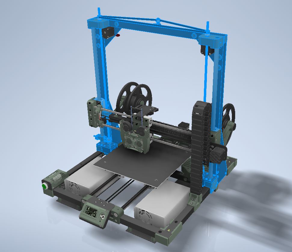
When needed, any such group can be extracted from the overall model and examined individually, down to each of its elements. These elements, in turn, can themselves be groups of objects or standalone entities.
This approach makes it easy to navigate through the 1,258 independent parts that make up the printer (assuming the object counter in the software isn’t lying):
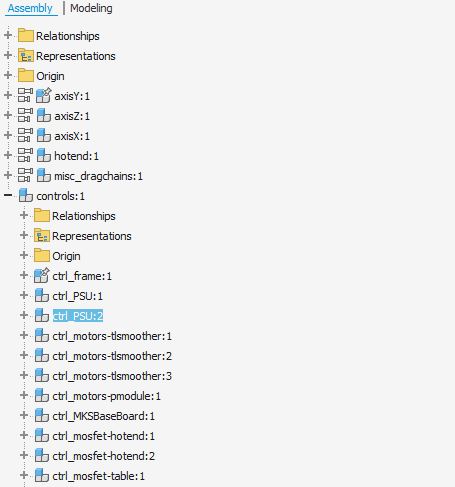
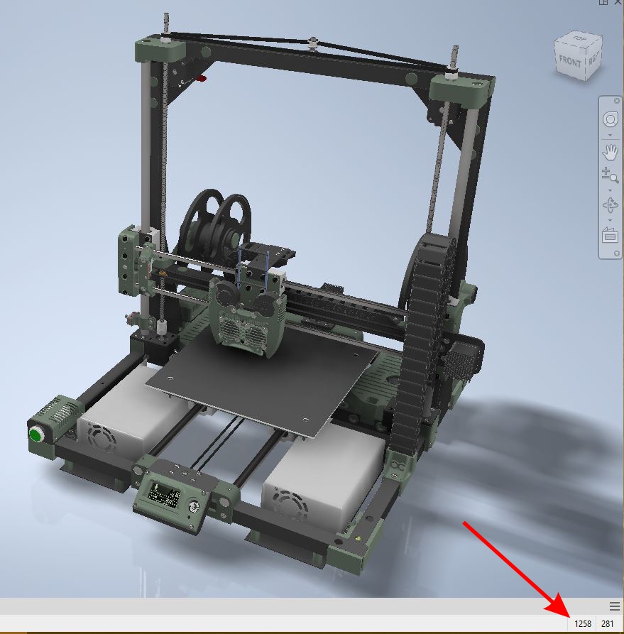
If you need to locate a specific piece in any printer assembly, it’s as simple as navigating the object tree and clicking each time on the group containing that piece — no need to struggle with remembering the name of the file where the part is stored.
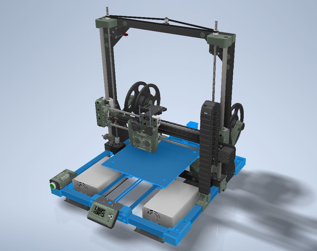
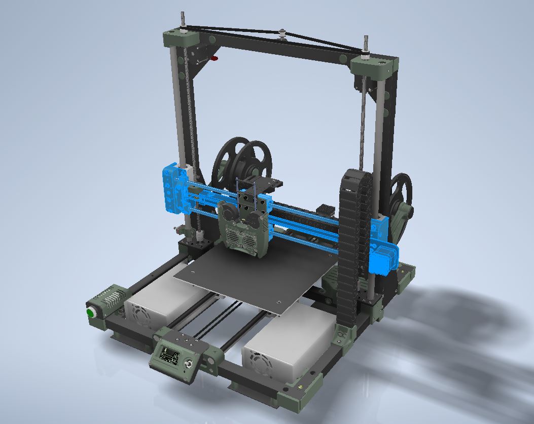
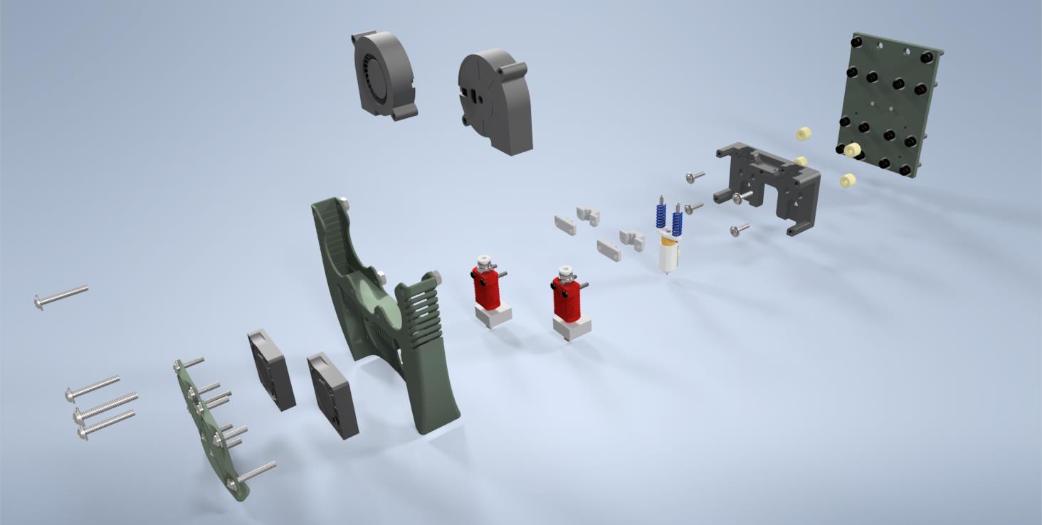
Let’s take a closer look at a group of components I’ve loosely labeled as the “printing assembly”:
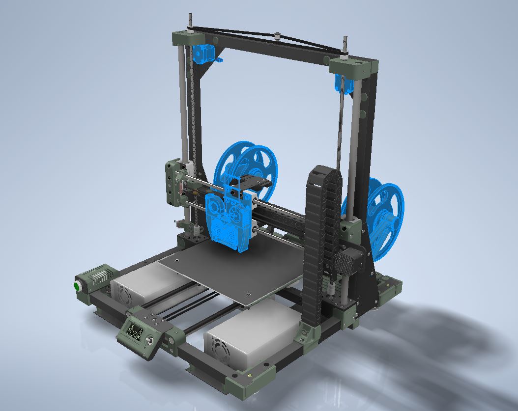
Without any need for visual cues or annotations, it’s immediately clear what the core elements of this group are: the filament spools mounted on holders at the rear of the printer, the filament feed motors for each spool located at the top of the printer, and the print head prominently positioned at the center foreground. While these main elements are not physically connected to one another, they all serve a unified purpose: to take a piece of plastic, deliver it to the heating element, melt it, extrude it onto the print bed, and cool the resulting output.
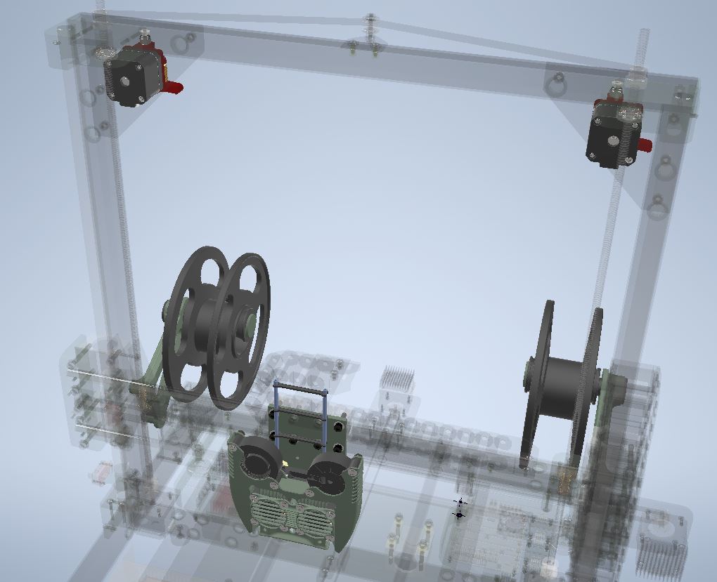
In the 3D model, every object is represented exactly as it exists in real life. Each part has precisely the number of screws and nuts it needs, exact virtual dimensions that match its physical counterparts, and is interconnected in a way that allows for realistic motion on the screen, just as it would in the real world. Everything is presented with meticulous accuracy — except for one thing: the filament feed tubes. These are represented in a more abstract manner:
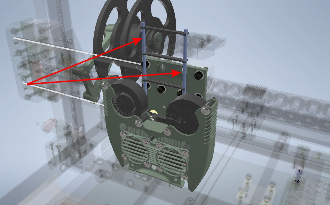
As in, “They exist, and they start from here.”
I could have modeled them to scale, extending from the print head to the feed mechanisms across the entire printer. However, doing so would have made working with the model significantly more cumbersome. Constantly adjusting and examining the model to ensure there are no conflicts during motion — ensuring one component fits with another, and that some unexpected screw head doesn’t collide with another part — becomes impractical. These types of conflicts are simple and quick to fix in the drawing stage but much harder to address on the physical device in the workshop. A small oversight in the model could lead to hours of extra manual labor. Consequently, the more I manipulate the model with the mouse, the less I have to manipulate it with a file on the workbench.
The filament feed tubes are among the few flexible components in the printer. Around 99% of the other parts are “rigid”—they don’t change shape no matter how you move them. Pull one rigid part with the mouse, and all the connected parts follow along seamlessly. Modern desktop computers can handle such calculations effortlessly, even on modest configurations. But these tubes are flexible. When they move, and as all objects connected to them also move, it’s not just their relative coordinates that change—their very shape is altered. The computer has to recalculate every polygon and vertex comprising the tube model, account for material resistance and deformation properties, check for surface intersections (both internally and with neighboring objects), and even factor in a simulated gravitational force that influences the direction and shape of each segment of the model.
These computations demand significantly more processing power. A quick mouse movement (even an accidental one) can trigger a chain of events that takes the computer seconds—or even minutes—to process before displaying the next frame. As a result, quick manipulations of the model become anything but quick and certainly far less comfortable. No matter how much one might strive to create a perfectly accurate project model, certain compromises must still be made for the sake of usability.
Whether filled with compromises or not, it was finally time to take all these components out of the computer screen — and place them on the workbench.
This process began with the print head block — as it is the most complex part, composed of elements where each plays a critical role in this circus:
The most crucial element here can be considered its base, which has a rather intricate shape:
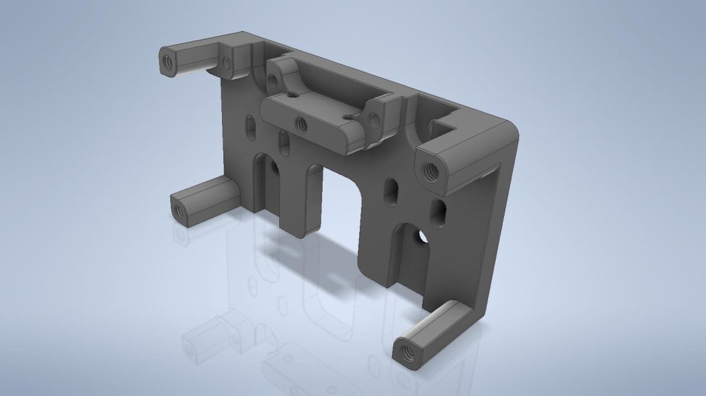
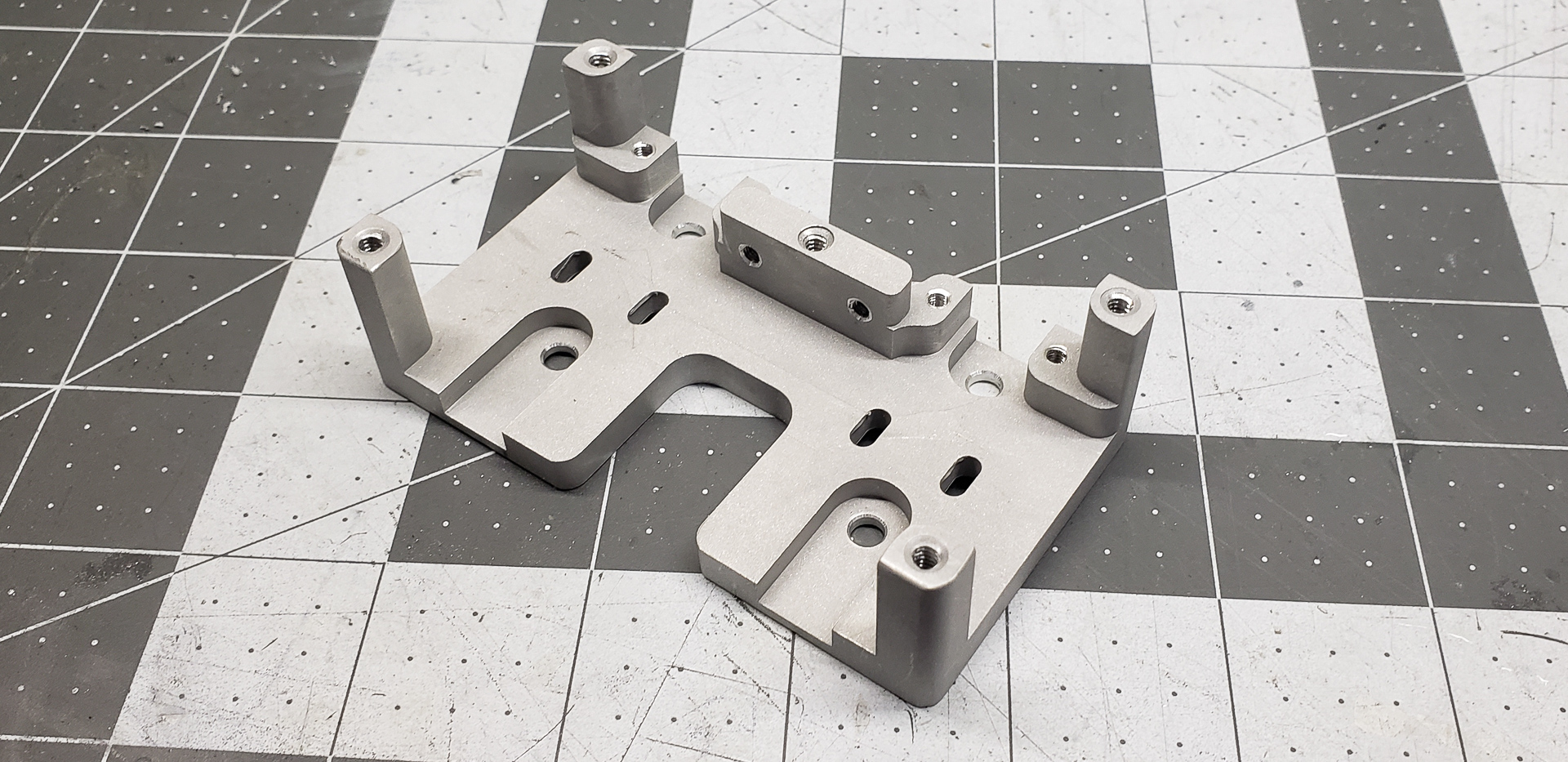
The most challenging part about this base was that it had to be made perfectly on the first try — without any errors. First, I had only one remaining aluminum “brick” left from the batch I had purchased for the project. But that was just half the trouble — I could always buy more (albeit at the cost of time and money).
Far more critical was the fact that the allocated personal-use hours on the company’s CNC milling machine were about to run out. At home, there was no way I could carve out such a complex shape. I had literally two or three Saturday hours left to manufacture this final part on the company equipment. Immediately afterward, the machine — without a moment’s rest — would be switched to production mode for company orders, running nonstop for the duration of the client contract. There was no telling how long I’d have to wait for another “window” to slip in my personal project.
That’s precisely why I wrote so much earlier about creating a complex yet precise model. Without this part, the entire project — yes, the entire 3D printer project — would lose its meaning. All the time spent so far would have been wasted. The project’s not-insignificant budget would have gone up in smoke. That’s why everything had to be taken into account, not just for this specific part but in terms of its interaction with all the other printer components — both those already completed and those yet to be made. Every single detail needed to be thoroughly tested and reviewed at least a hundred times in the model. There was no time for a second attempt.
I think it’s obvious to everyone that I succeeded. Otherwise, this article series wouldn’t exist. Nor would that grumbling printer with the odd name Marsh Turret — which is currently brooding over its latest protective panel for the electronics.
The base itself is attached to the X-axis carrier platform in a straightforward manner — with four bolts and nylon spacers:
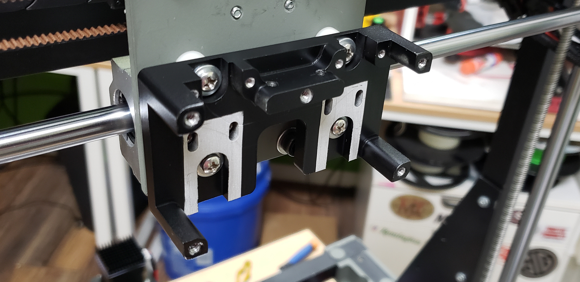
What’s far more interesting is everything that gets mounted onto the base:
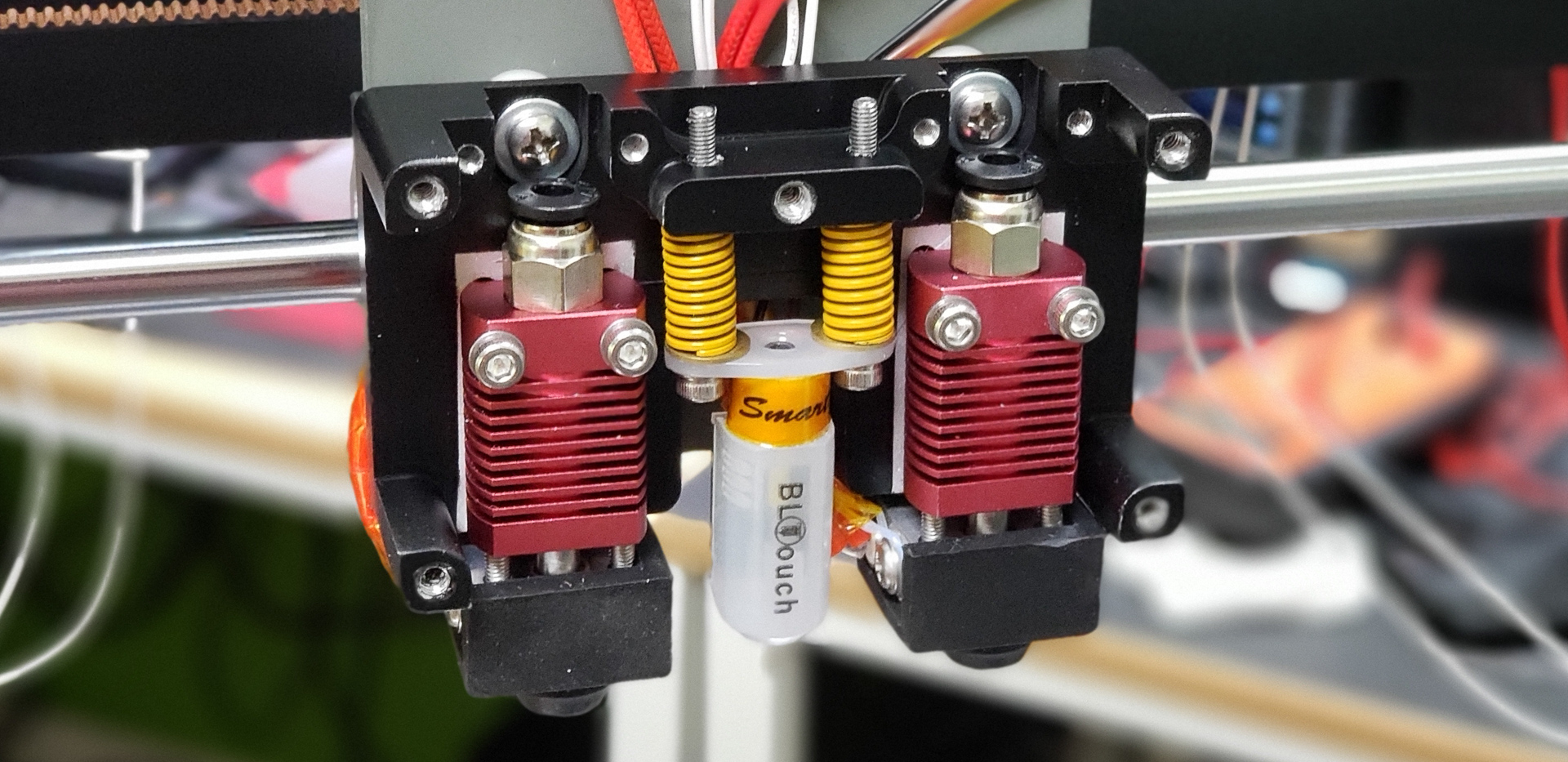
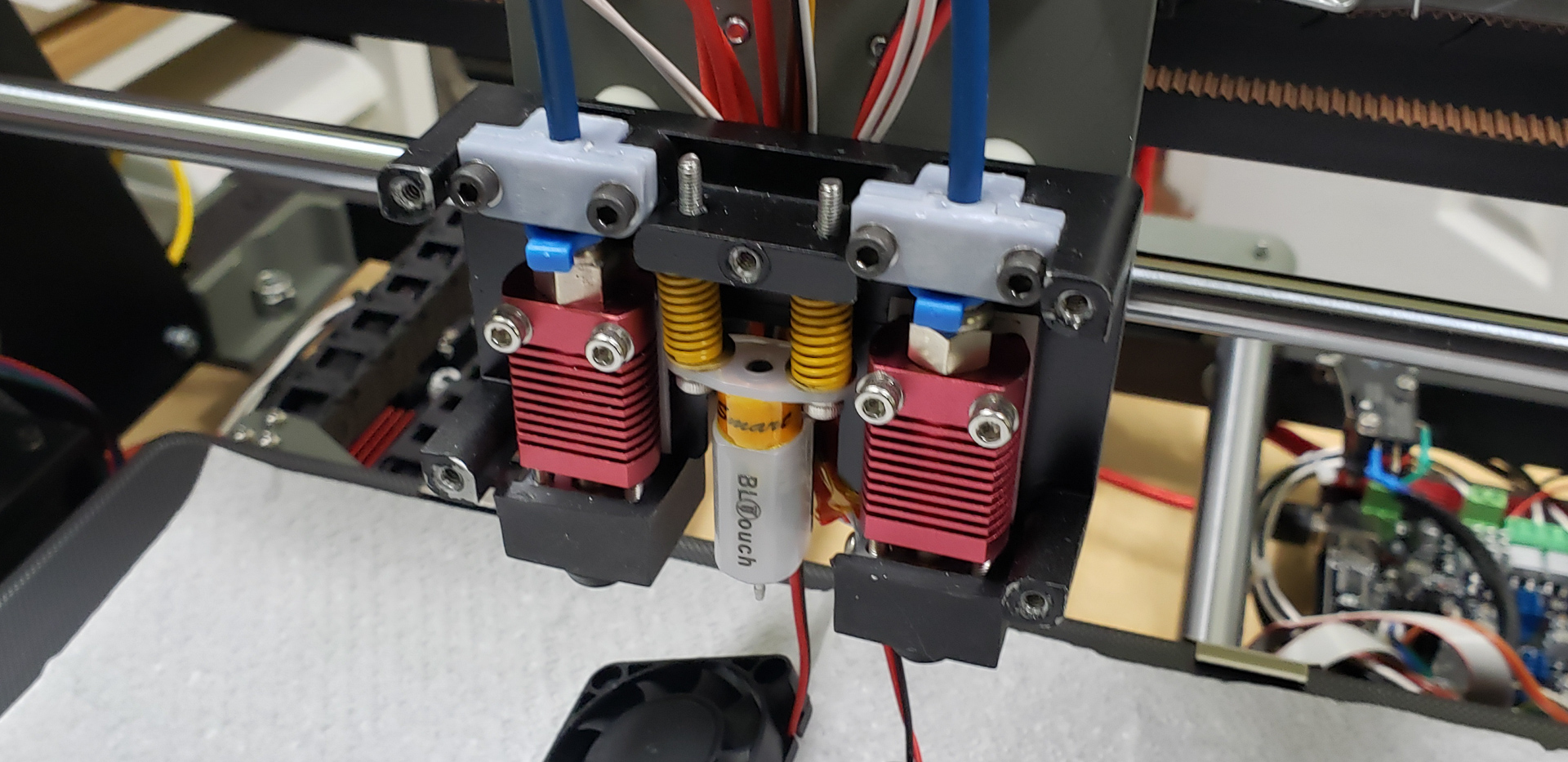
At the center, there’s something resembling a small syringe — this is the BLTouch. It’s a probe sensor that allows the printer to “feel” the entire print bed surface before starting a print. With this data, it can determine not only the zero point for the Z-axis but also any potential unevenness across the bed, which can be accounted for and corrected during printing. Flanking the probe are the print heads, equipped with their respective radiators and heaters.
The intricate design of the mounting base must not only hold these three key components together but also allow for precise adjustments. This is critical! The nozzle tips of the print heads must be perfectly aligned at the same height. If not, the second nozzle might scrape off the material deposited by the first, or worse, it could dig into the printed layer and block the printer’s movement entirely. Either way, the print would be ruined.
The distance between the nozzles is equally important. In this case, it’s exactly 50 mm. While it’s possible to adjust this value in the printer’s firmware, I prefer to avoid dealing with odd numbers like 49.34 mm. A clean, even number like 50 mm is both aesthetically pleasing and practical, and there’s no reason not to set it precisely during the installation of the print heads.
The vertical distance from the BLTouch probe tip to the nozzle’s end is another critical parameter. If this isn’t set accurately, the printer will print either above or below the level “felt” by the probe during its operation. Again, this can be adjusted in the firmware, but such settings are meant for fine-tuning, such as compensating for minute discrepancies caused by nozzle heating, not for the primary calibration of the assembly.
These adjustments don’t need to be made often — only during nozzle replacements or after particularly catastrophic incidents (like the time a cat decided to nap on the printer’s warm bed mid-print — true story from the Black Widow, where the entire X-axis was knocked completely out of alignment). For such occasions, I’ve created a special tool, which I’ll discuss in the “Accessories” section of this article series. It significantly simplifies the calibration process and makes it nearly foolproof.
Next up… Bowden tubes for filament feeding.
These were something entirely new to me. Until now, I had never dealt with this method of delivering plastic to print heads, and I had to learn a lot about the pitfalls in this area. Thanks to the internet, I didn’t have to discover all these pitfalls the hard way.
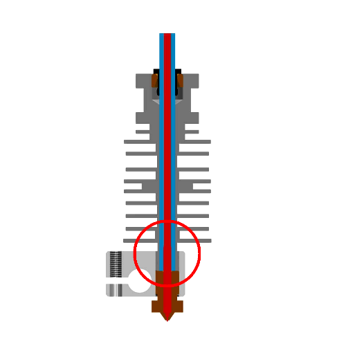
It was immediately clear that these tubes should enter the print heads as vertically as possible and that their ends needed to be perfectly flush to ensure there’s no gap between the tube and the nozzle:
What was less obvious (though somewhat expected) was the fact that the fittings meant to hold the slippery PTFE tubing in place aren’t all created equal:
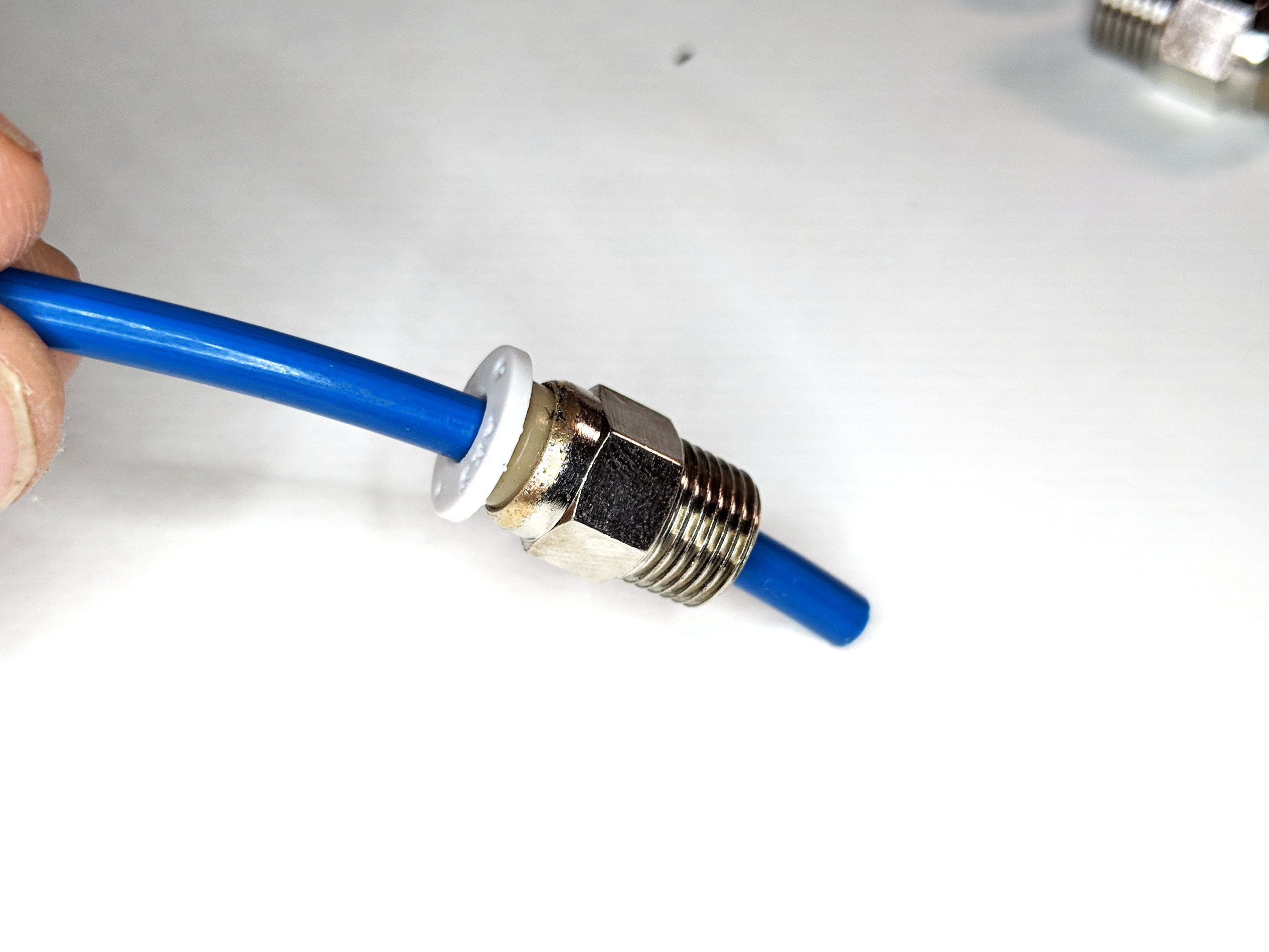
That’s putting it mildly… The overwhelming majority of fittings that come bundled with print heads are nothing short of useless junk! One way or another, the tube wiggles, twists, bends, and generally behaves like a worm on a frying pan. A standard cheap Chinese fitting usually lacks the “backbone” to keep the tube firmly in place and prevent it from misbehaving. Inevitably, a gap forms between the tube’s cut and the nozzle, where molten plastic builds up. The extruder thinks it has pushed out a certain amount, but in reality, some of that material doesn’t come out of the nozzle — it simply fills the gap, squishing around like oatmeal in Sir Henry’s boot. This leads to gaps or over-extrusions in the print.
Thankfully, I didn’t have to experience this disaster myself. After seeing plenty of examples from others, researching the topic, and heeding advice, I invested in a high-quality set of fittings recommended by “leading printer experts.” I made the right choice! These fittings feel noticeably sturdier than the ones that came with the print heads. The “collars” you press to release the tube click distinctly, like good buttons on an old-school mechanical keyboard. Meanwhile, with the stock fittings, you can barely tell if you’ve pressed the miserable thing or not…
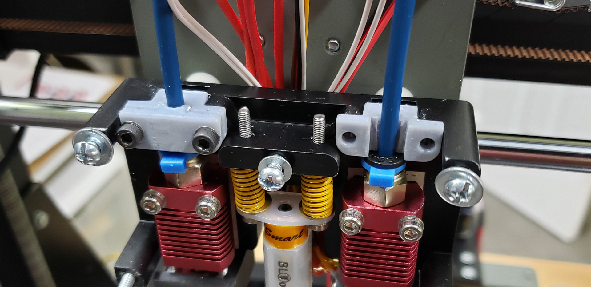
But I didn’t stop there. If you look at the photo above, you’ll notice that before the tube even reaches the fitting, it passes through another clamp (the gray one). With this additional mount, the tube has absolutely no chance to wiggle in its seating. When the screws on this secondary clamp are tightened, all possible lateral forces are removed from the fitting on the print head. This way, the fitting handles only pulling forces, while the additional mounts absorb any side-to-side stresses. Together, they hold the tube so firmly that it has no chance of going rogue.
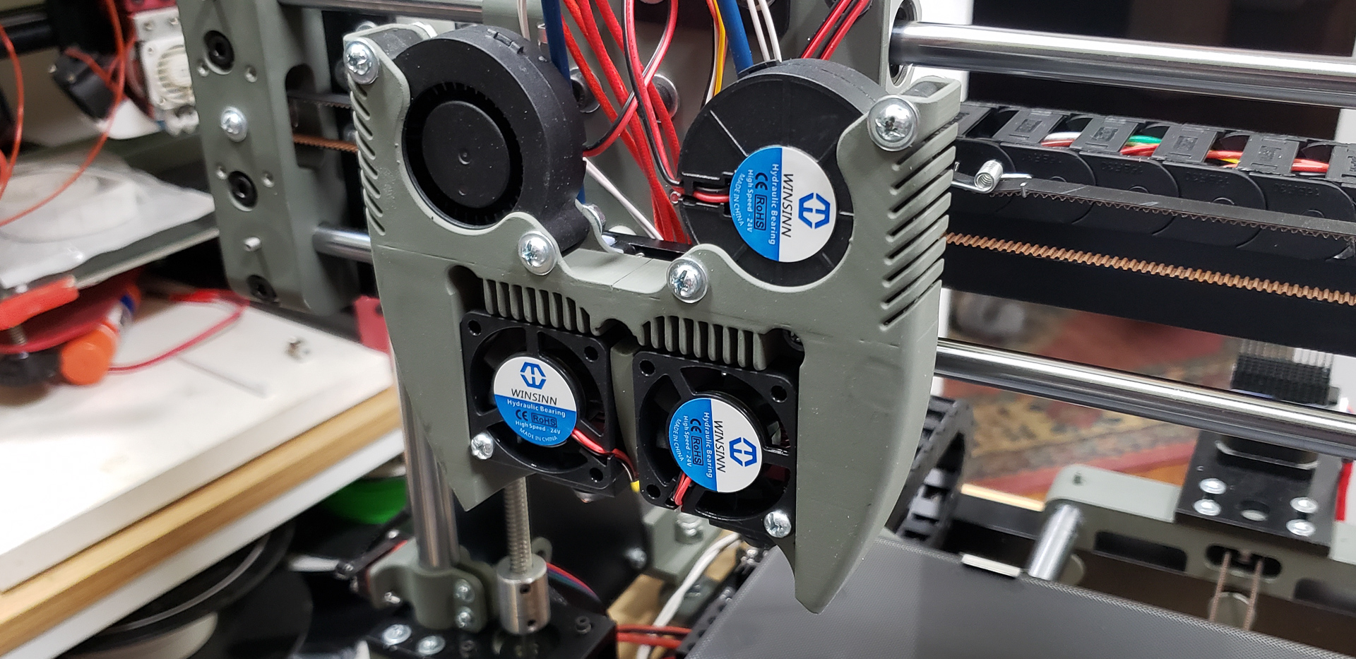
Somewhere around this stage, the puppet finally turned into a real boy. For minimal 3D printing capabilities, all it took was temporarily attaching a couple of fans — on a wing and a prayer — to cool the radiators of the print heads:
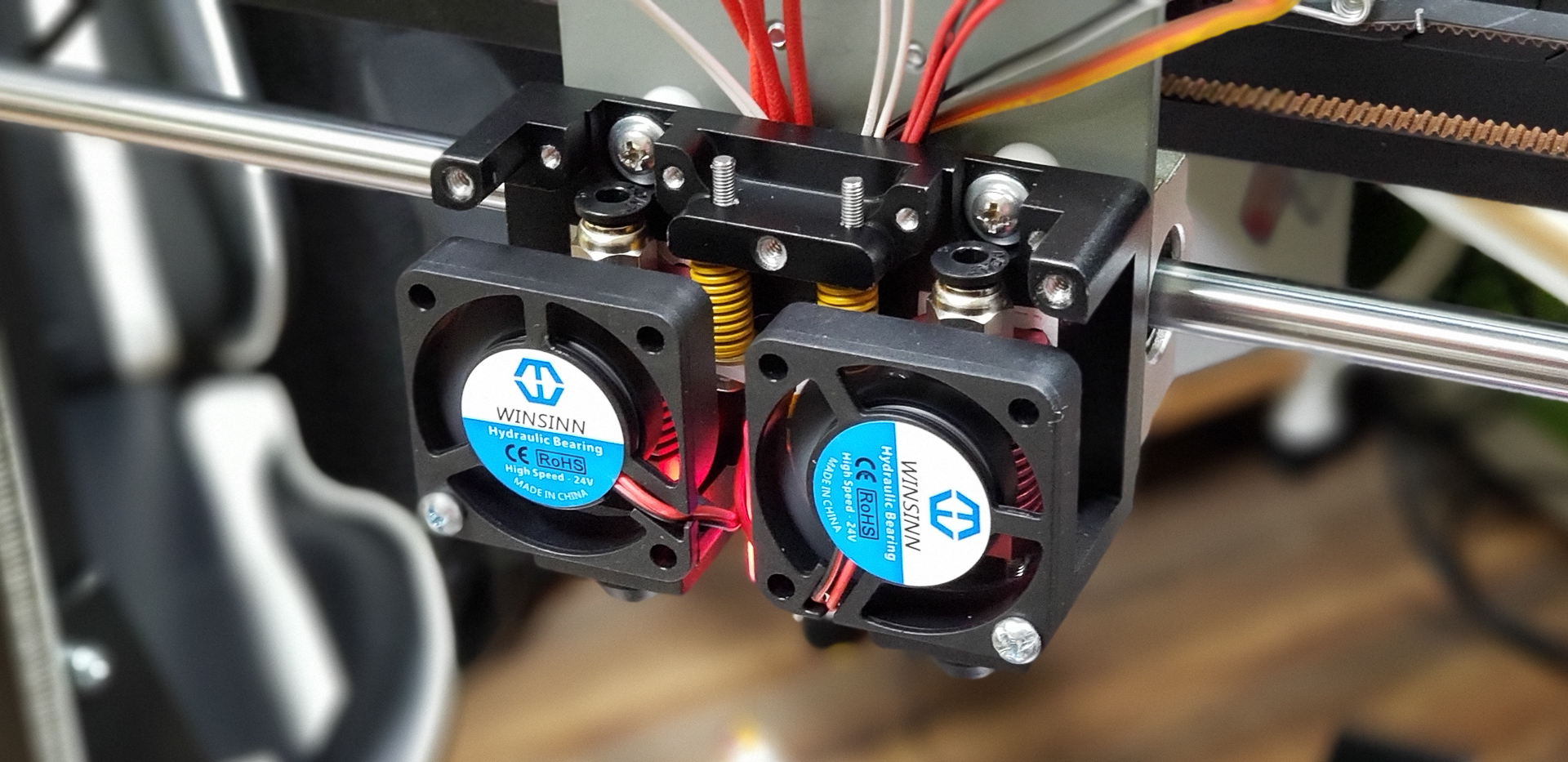
That’s it! The printer was already capable of doing its job. It could even attempt printing something super simple…
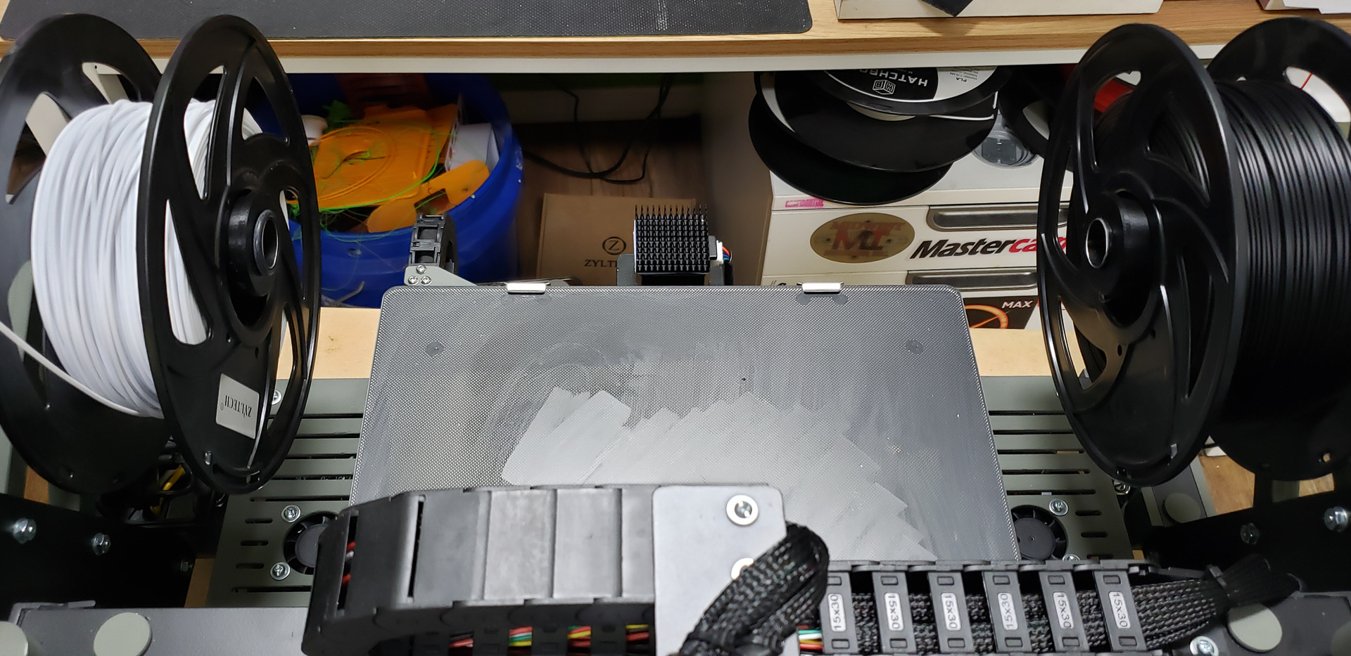
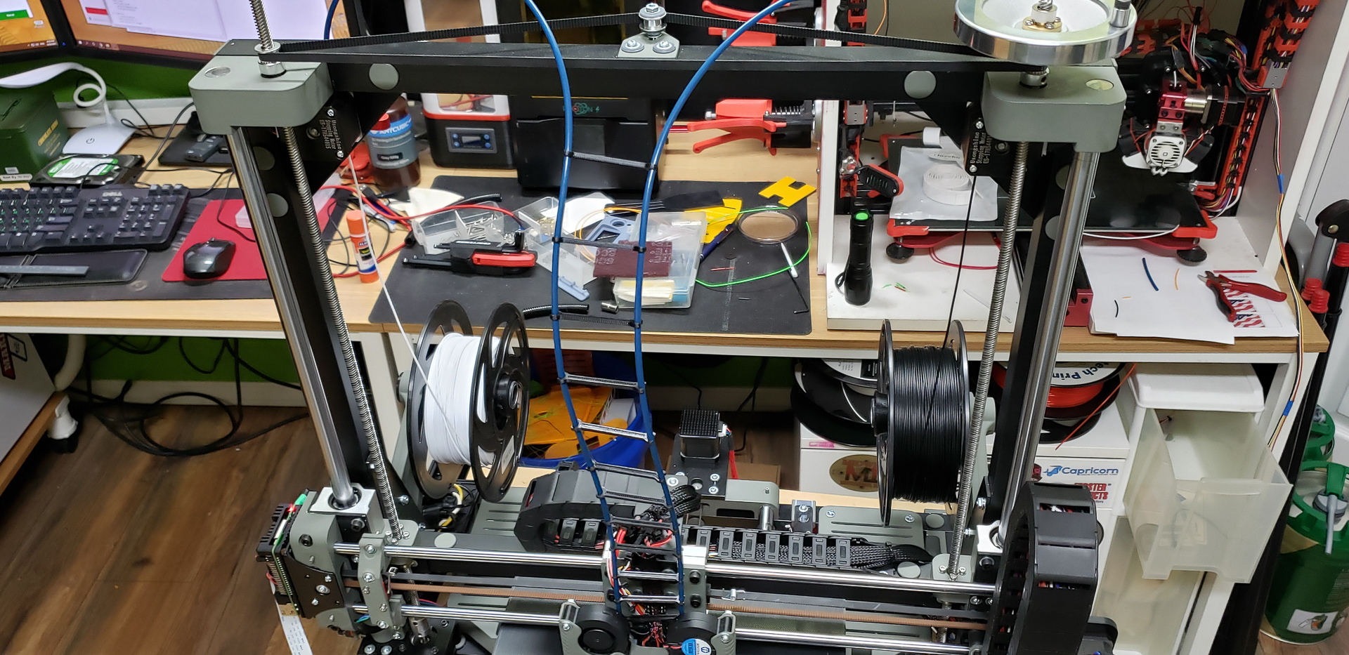
At that point, since the printer still didn’t have its own spool mounts for filament, the “feeding mother” turned out to be the frame of the old Black Widow standing next to it:
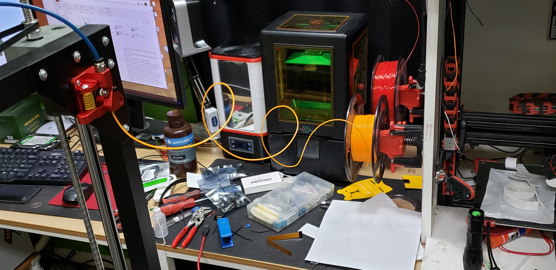
This gave my friend — who was closely following the project — plenty of material for snarky comments, like tabloid-style headlines: “The corpse of the old Widow feeds the new marsh!” and so on.
The system for feeding filament from the spool to the print head was completed back during the assembly of the Z-axis. While it doesn’t logically belong to the Z-axis group, it made more sense to install it at that stage for easier assembly.
For the filament drive, I opted for more advanced dual-gear extruder blocks with a shared gear coupling between the two shafts:
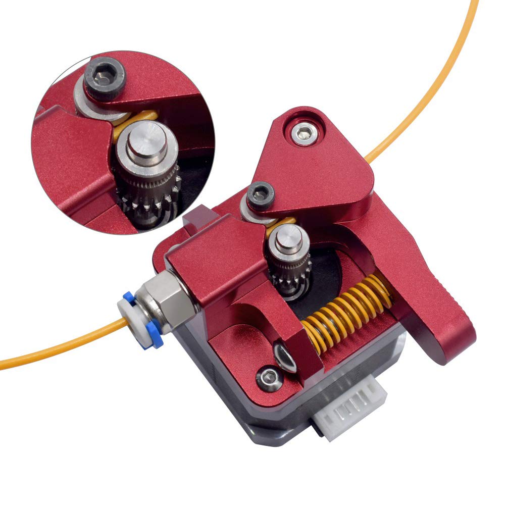
By comparison, the old Black Widow only had a single drive shaft. It pulled the filament by pressing it against a polished passive roller on the opposite side. Despite the Widow’s extruder motor being equipped with a reduction gear, the filament still couldn’t be fed through the nozzle with much force. The shaft would simply slip against the filament, failing to push it into the “combustion chamber.” To compensate, I had to heat the plastic significantly above its normal working temperature to increase its flowability.
For example, I had to overheat PLA all the way to 235°C — which is utter nonsense, considering its typical working temperature is 190–210°C. Honestly, 235°C is even too much for ABS. At that temperature, PLA was practically on the verge of disintegrating.
Somehow, I managed to adapt back then, and it worked… But for the Marsh Turret, I decided not to adapt to anything. Instead, I adapted the printer itself for proper operation from the start.
On top of the dual gears, I installed full-sized NEMA 17 motors for filament feeding instead of the smaller “cut-down” versions (like the 17HS12-1204S and similar) commonly used. These are the same motors that power the entire movement system of the printer.
Yes, it’s overkill. Yes, sometimes it feels like the extruder could push filament through the nozzle without even melting it. But I’d much rather deal with that than the chronic under-extrusion I constantly fought against with the Widow.
Of course, the journey didn’t end there. A few temporary fans and feeding filament from the Widow’s “corpse” were all well and good, and I even allowed myself almost a week off to tinker with the Marlin firmware. At long last, I could work with a printer that physically existed!
However, the print head assembly was still far from complete. Beyond fixing the “temporary fan setup” into something more permanent, the print head also needed a proper layer cooling system and some lighting.
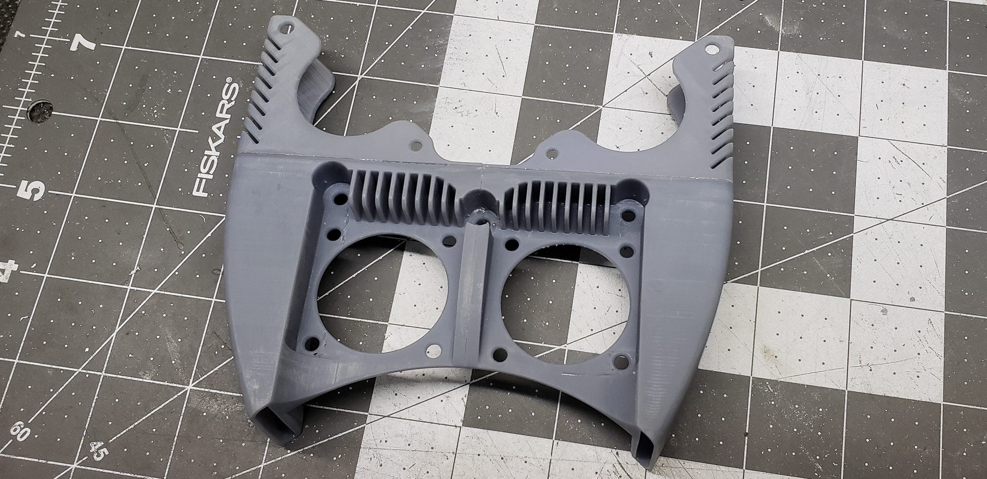
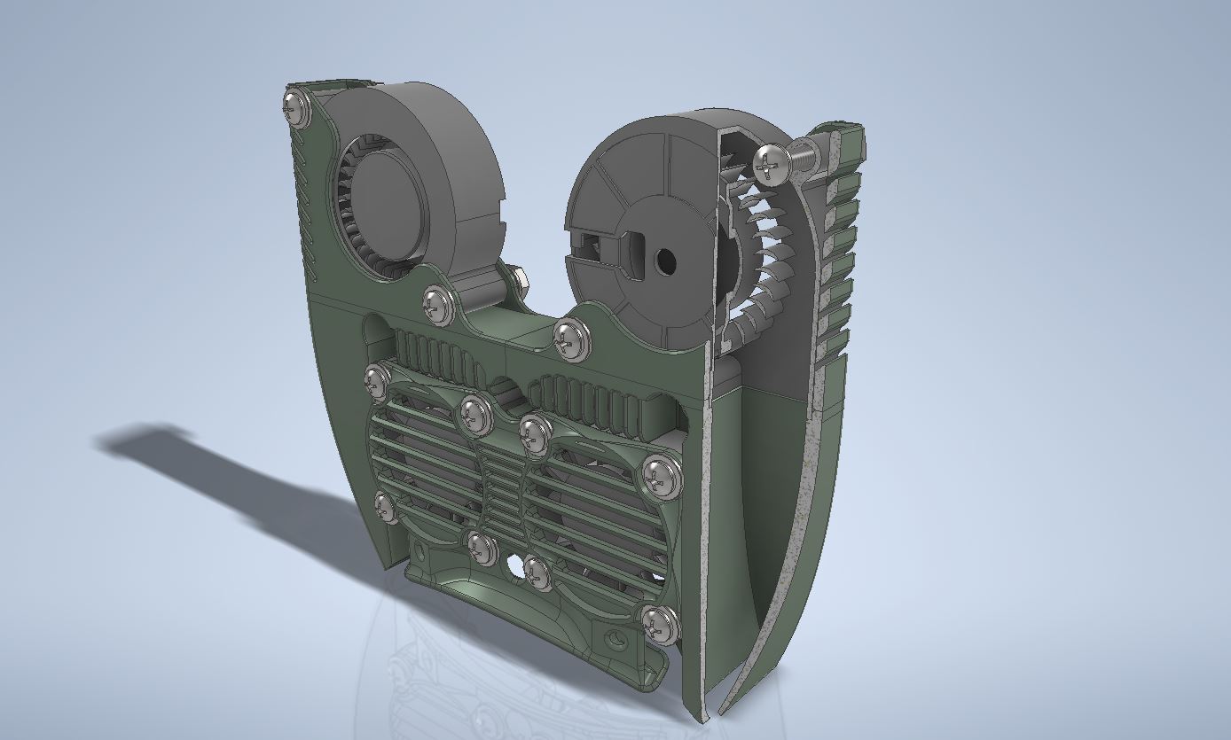
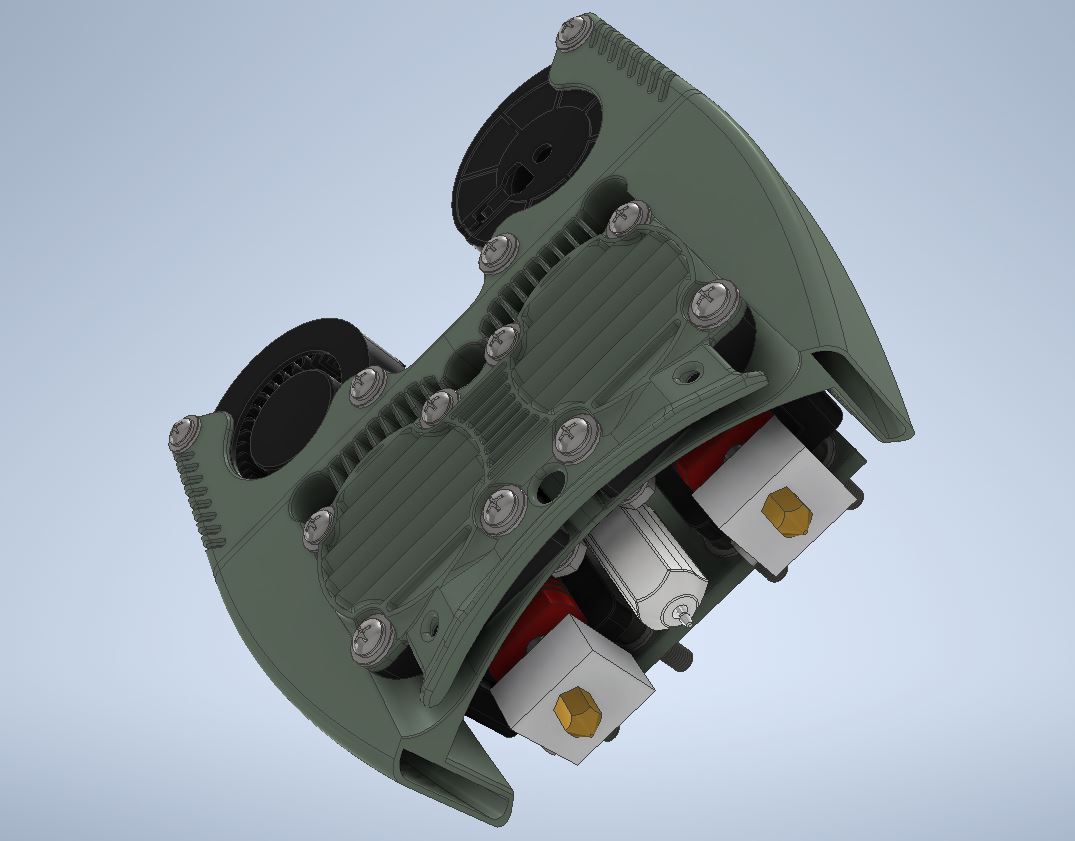
For this, I designed a custom attachment for the print head assembly. To ensure ease of maintenance in the future, this part was made fully removable and self-contained:
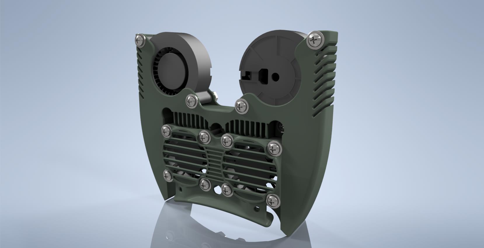
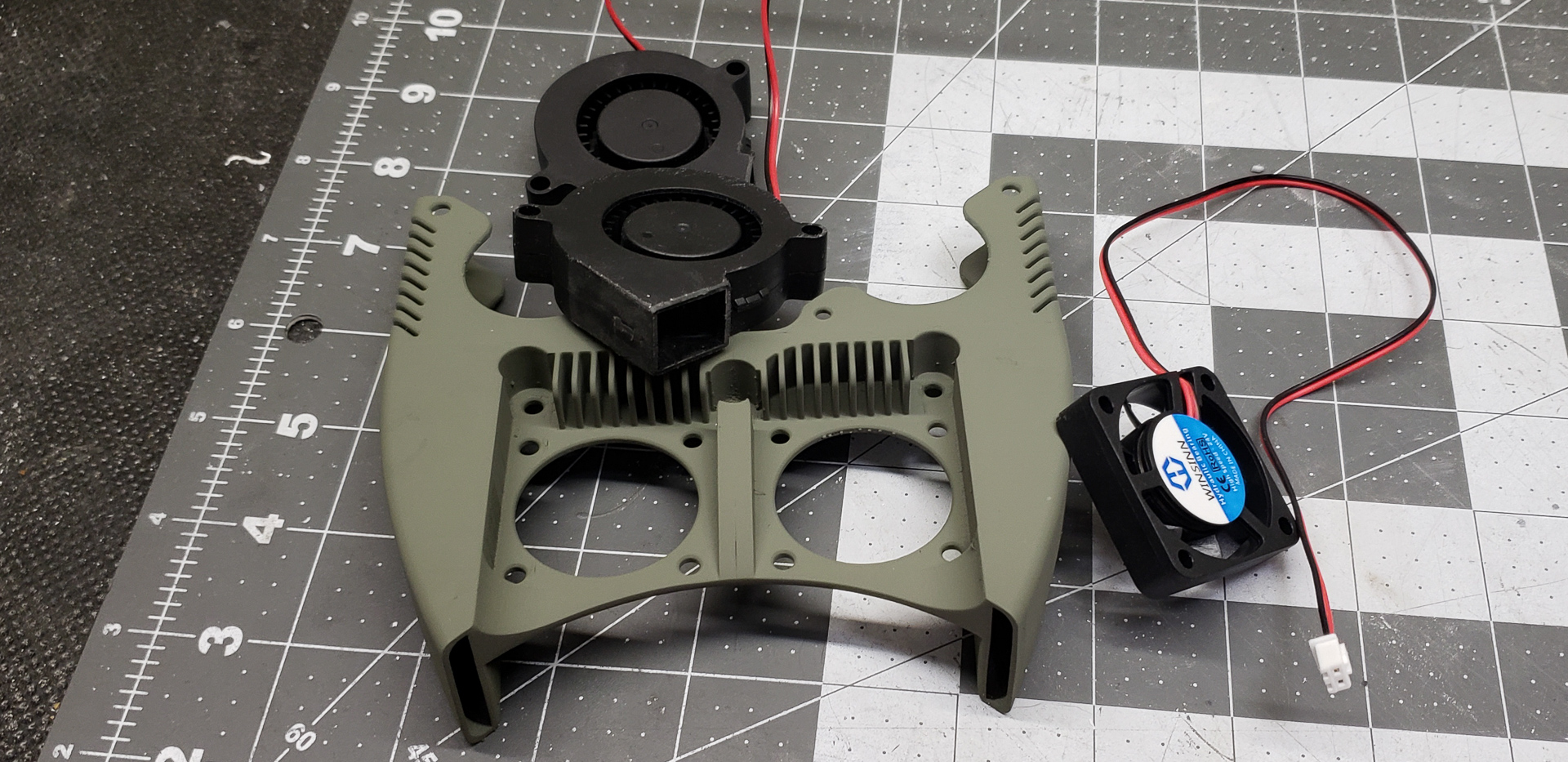
This module incorporates no less than four fans: two standard fans for cooling the print head radiators and two “blower” fans for cooling the printed layers.
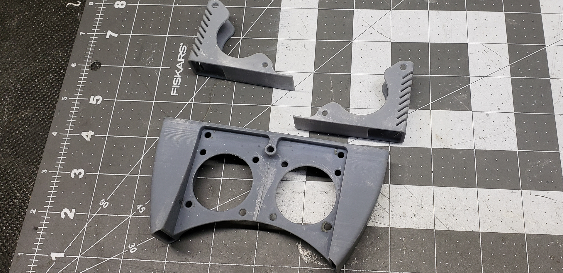
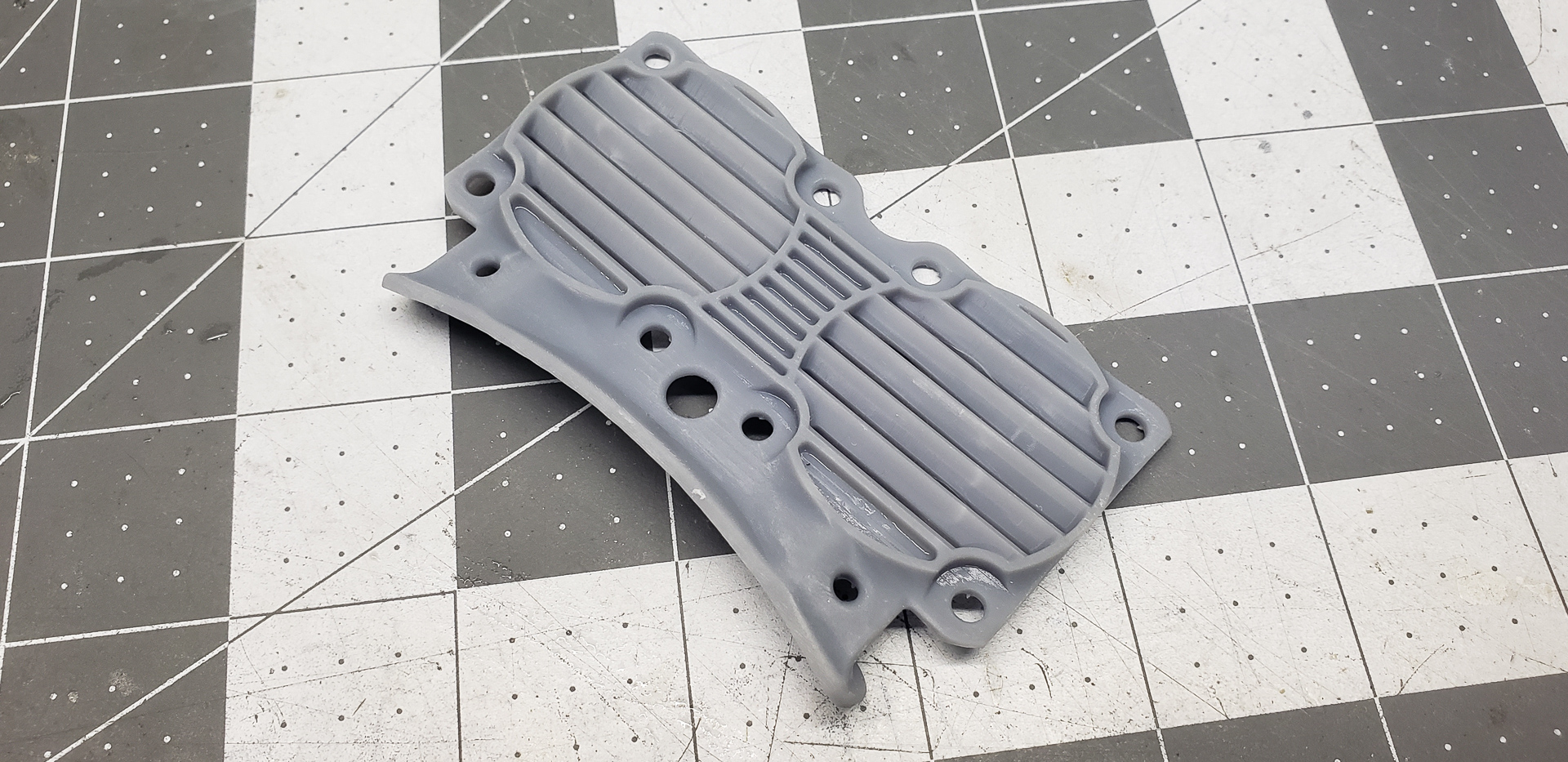
Naturally, the base for this construction wasn’t made from aluminum using a CNC machine. Given the internal geometry of the air ducts, that would have been far too labor-intensive.
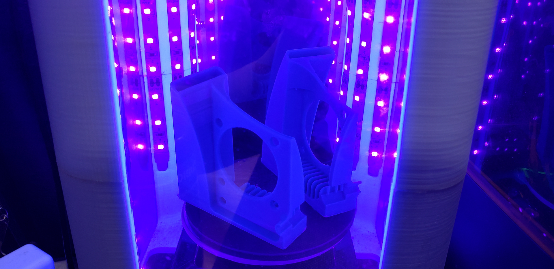
Instead, all the parts for the fan modules were produced on my photopolymer Photon printer.
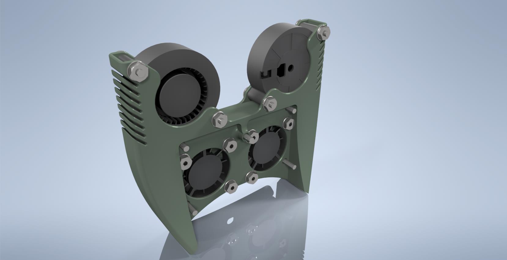
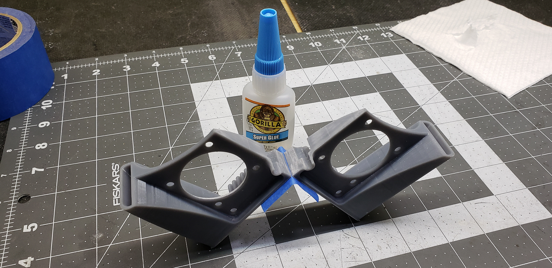
While that worked out fine, the Photon’s resin vat limits the maximum print size, which isn’t very large. In theory, I could have squeezed the housing into two parts, but I decided to play it safe and split the structure into four sections, which could be printed in pairs:
After printing, the parts were glued together to form a single unit:
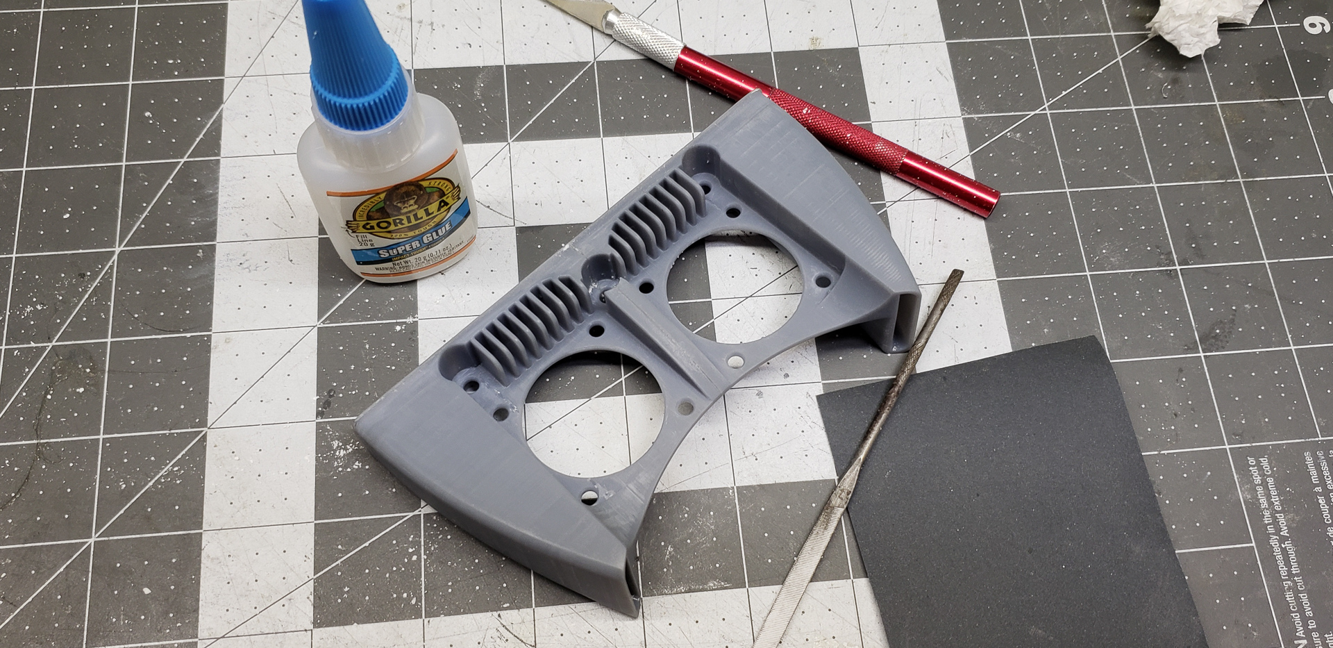
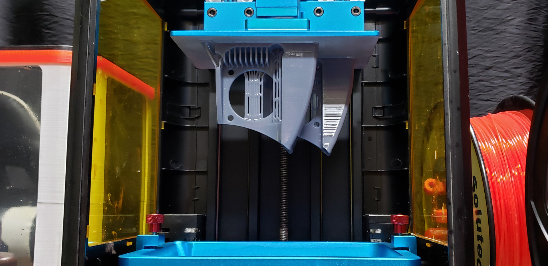
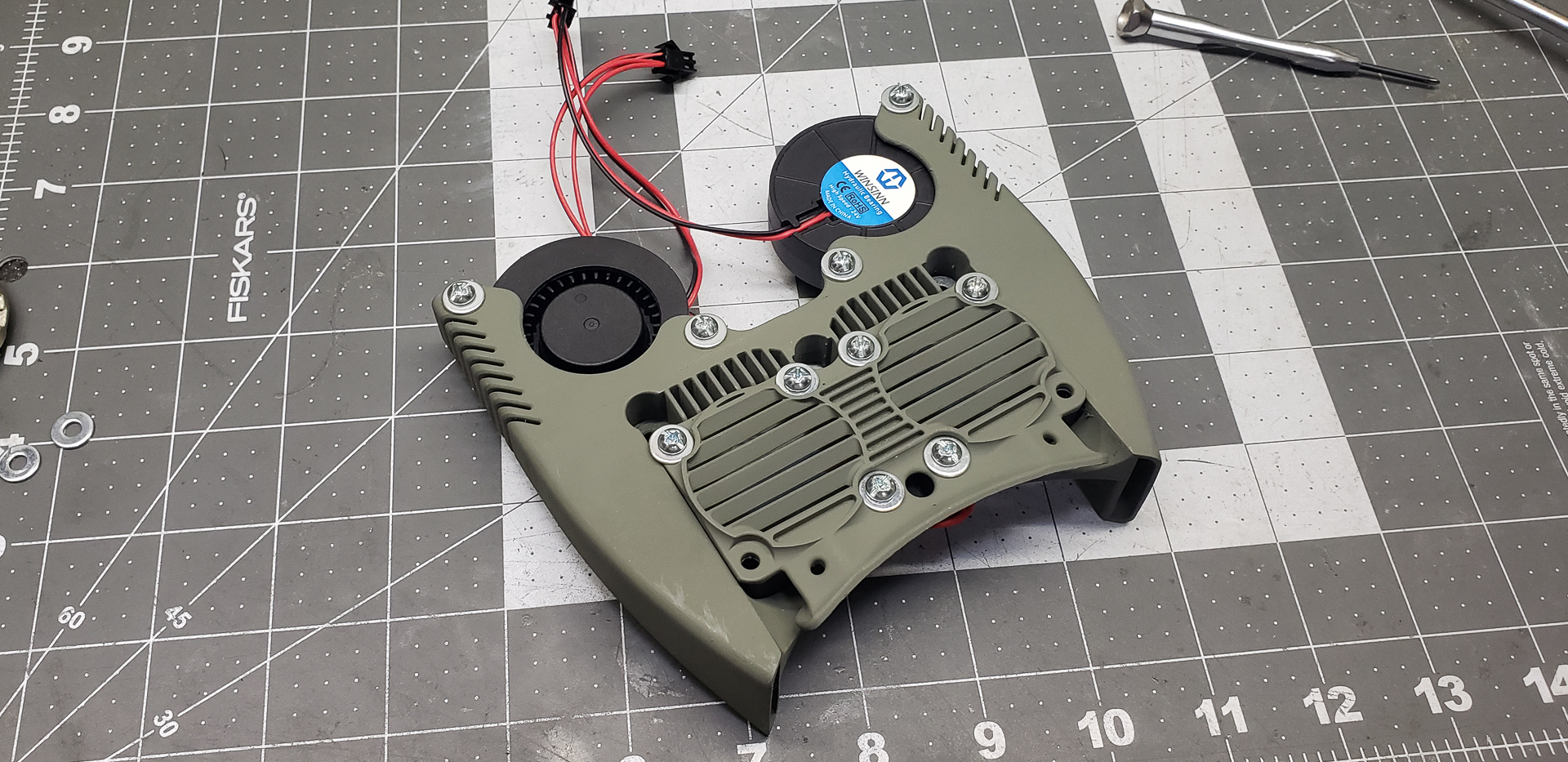
Painting, assembly, and installation followed:
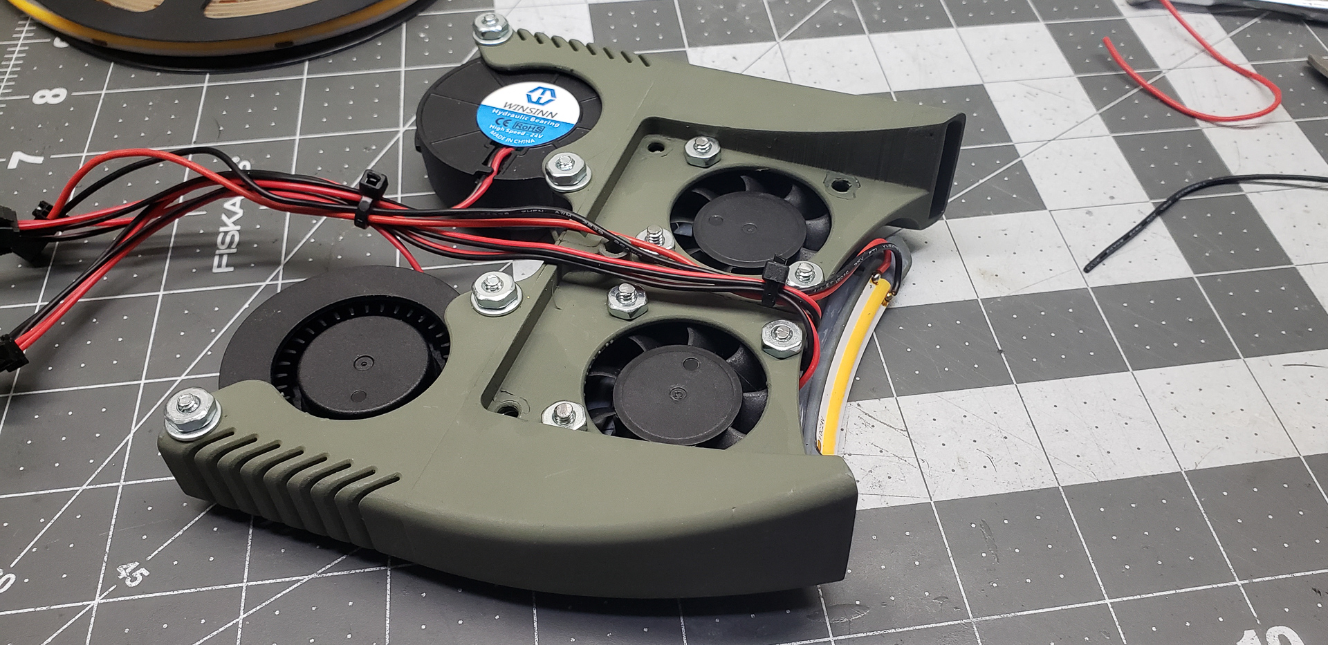
I reused the same clever trick for the print head radiator fans that I had previously used on the Widow.
Under normal circumstances — when the heating block is functioning properly, equipped with a suitable heat break tube, and printing occurs within a stable temperature range — the radiators of the print head barely warm up. They feel just slightly warm to the touch and don’t require intense active cooling. A gentle airflow is more than enough to prevent heat buildup.
If the radiators become so hot that you can’t touch them and need constant, intense cooling, something is seriously wrong with the system. The problem isn’t the airflow — the issue lies within the print head itself. Such overheating of the radiators is abnormal and must be fixed.
Typically, the cooling fan is mounted to blow air onto the radiator. At first glance, this seems logical. However, in practice, the airflow from the fan breaks against the radiator and assembly, scattering in all directions. Most of it ends up blowing directly onto the print bed, simply because there are fewer obstacles in that direction.
When printing with plastics like PLA, this isn’t an issue. Such materials benefit from cooling during printing and often require additional cooling systems. But things are very different when printing with ABS or similar plastics. Forced cooling during printing is a disaster for these materials. They shrink unevenly, causing the print to crack, delaminate, or detach from the bed, turning the print into a frustrating mess. For such plastics, it’s crucial to isolate the printing area from drafts entirely, allowing the part to cool gradually and uniformly. Clearly, a fan blasting air directly onto the print bed doesn’t contribute to a stable temperature environment.
To minimize this unwanted airflow, I “invented” a brilliant trick — I flipped the fan around. Instead of blowing air onto the print head, it now pulls air away from it. The radiator still cools effectively as air is drawn through it, but this way, the airflow from the fan becomes much easier to control and direct away from the print bed.
For instance, I added simple deflectors:
Эти шторки отфутболивают поток воздуха из вентиляторов вперёд и вверх подальше от стола.
These deflectors redirect the fan’s airflow forward and upward, away from the bed.
I’m fully aware that miracles don’t exist, and the laws of physics can’t be cheated. Reversing the airflow doesn’t eliminate it from the bed area entirely. The volume of air removed is still equal to the volume drawn in. However, now the air enters the print area not as a direct blast from the fan but as a diffuse flow from the surrounding volume. This “draft” is far less intense, much more uniform, and practically imperceptible.
Here’s an easy demonstration:
Notice how long the smoke lingers above the bed before it’s drawn into the fan and expelled upward. If the fan were blowing directly, the smoke would be blasted straight down onto the bed.
This simple fan trick dramatically improved my print quality with ABS-like plastics. Ever since flipping the fan on the Widow, I’ve had zero issues of this kind. It’s for this reason that I never completed the enclosed “aquarium” for maintaining a stable print area temperature in that project. The need simply vanished, and I had no desire to waste time on that “feature” anymore.
The same front-facing deflector that redirects fan airflow upward also serves as a mount for print area lighting — just a simple strip of LED tape:

Previously, I used bright “white” LEDs to illuminate the print area, which made the printing process on video look like welding. This time, I opted for a strip with less intense LEDs and a warmer spectrum… I don’t know… In my opinion, the improvement isn’t significant. Previously, it looked like “electric welding,” and now it’s more like “gas welding.” You can see in the photo that the top of the Benchy is completely overexposed. Warm and cozy, sure, but still overexposed.
Interestingly, this issue only appears on video. To the naked eye, the light looks perfectly fine — warm, even, and not overly bright, while still allowing you to clearly see each printed layer.
In any case, before tackling the overexposure issue on camera, I need to install all the planned lights on the printer. For now, it’s just a spotlight effect in a dimly lit room. Once proper background lighting is in place, I’ll reevaluate…
The layer cooling system utilizes powerful 50-mm blower fans:
The air ducts are directed straight at the nozzles:
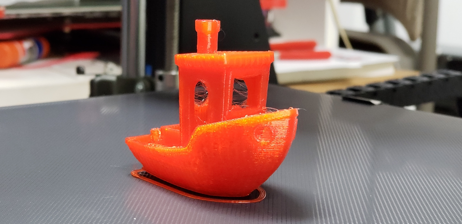
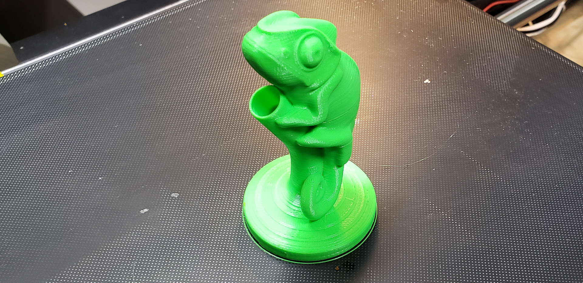
So far, this setup seems to deliver good results. Bridges and overhangs are coming out quite well. While I haven’t yet printed a dedicated test model for bridges and overhangs, early experiments suggest that angles of 30 degrees are a breeze for this printer (as seen in the bow of the Benchy keel just above the print bed, or the overhanging chameleon legs):
The Widow, on the other hand, struggled to hold a 45-degree angle from horizontal. Angles of 50-55 degrees were passable, but I generally avoided designing models with angles below 60 degrees. Overhangs were an absolute no-go because the plastic had to be overheated, as I explained earlier. It simply didn’t have time to cool, regardless of the layer fan intensity, and sagged. A bridge just a quarter inch long was the Widow’s limit. In contrast, even with rough settings and the fan running at just 50%, the Marsh Turret can easily handle bridges over an inch long.
I still plan to tackle a proper test model to fully explore this printer’s capabilities, but first, I need to fine-tune all the other printing parameters. The settings I developed over years of working with the Widow don’t suit this printer at all. The new printer is more precise, more stable, and faster. All the tweaks and adjustments I used to compensate for the Widow’s design flaws are now more of a hindrance than a help. This part of the project is still a work in progress…
The print head is ready, the filament drive is set up — now it’s time to address the spools. The Turret can’t keep borrowing filament from the Widow forever…
The spool holders on the Widow were absolutely insane. There were four of them, and I must have designed them during some particularly wild fever dream.
The idea was that the mechanism would self-center the spool on the axis, ensuring smooth and free rotation:
And it worked exactly as intended. It perfectly centered spools of various brands with different hole diameters, providing gentle and effortless rotation. It was practically flawless… Except it wasn’t. The problem was that this brilliance caused more harm than good.
The moment the printer tugged on the filament, the spool would start spinning — and keep spinning, even after the printer stopped pulling. This was especially problematic with new, full, and heavy spools, which could build up a substantial amount of momentum. Naturally, there were times when the spool, continuing to spin freely, would start unwinding and dumping loops of filament, which then tangled themselves into a chaotic mess. I had overengineered it…
This time, I decided to keep it as simple as possible!
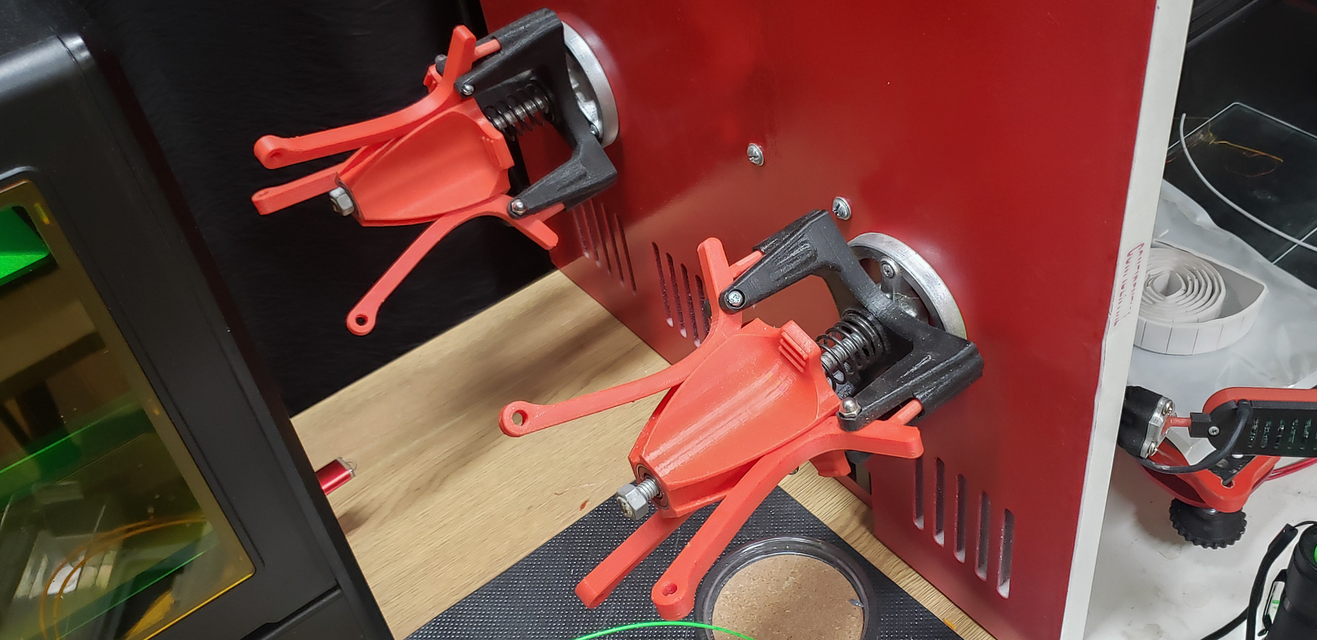
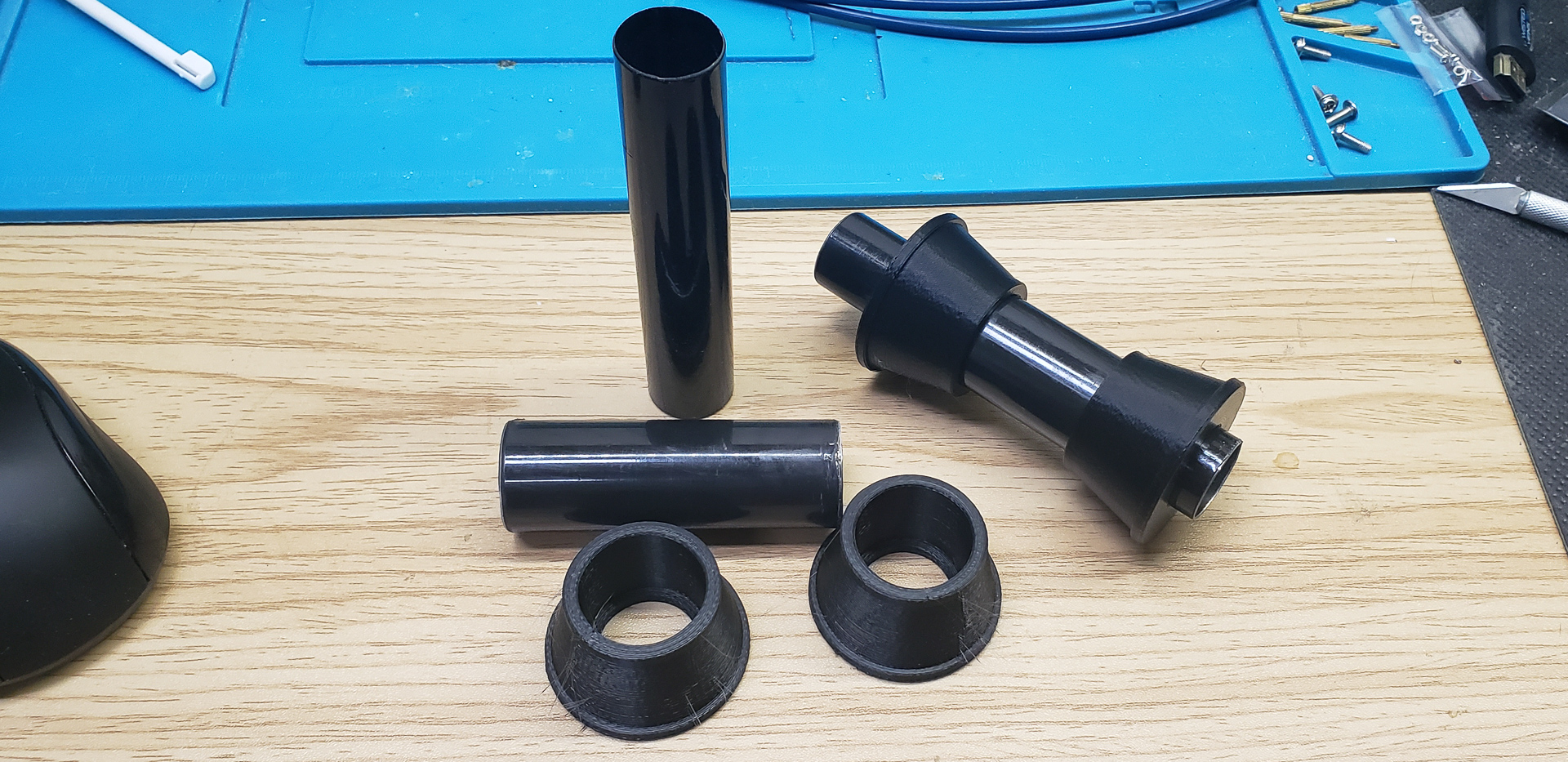
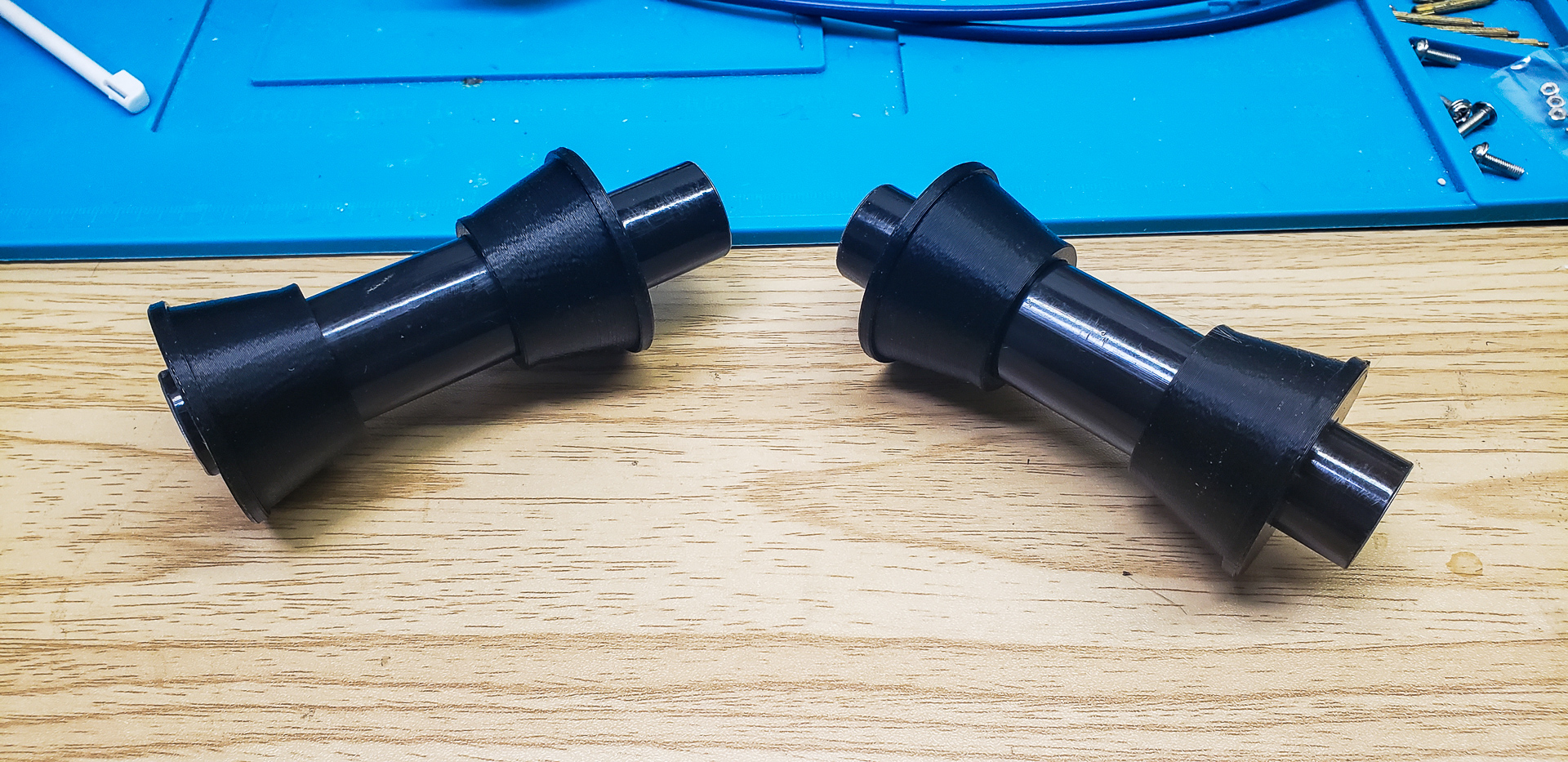
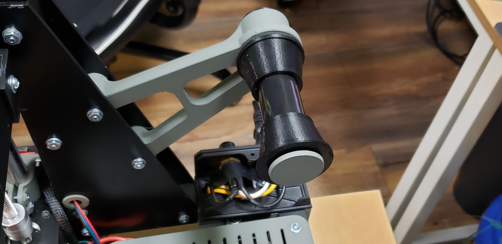
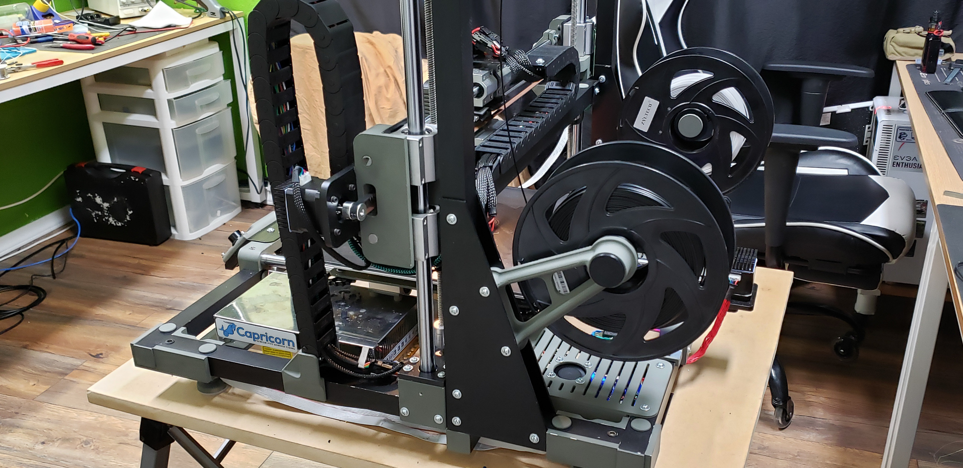
Just a simple arm attached to the printer frame, an axis, a sleeve (with no bearings), and side stops to prevent the spool from falling off:
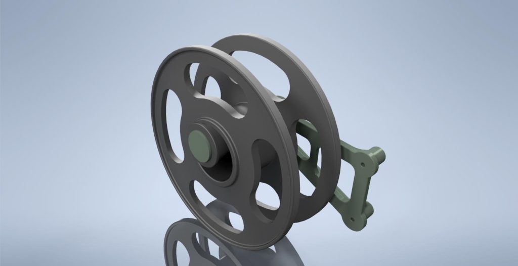
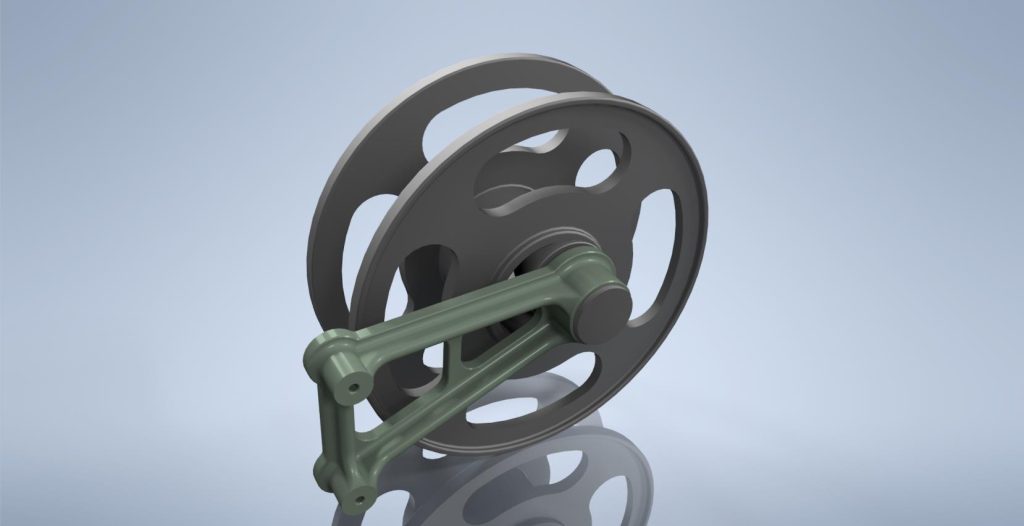
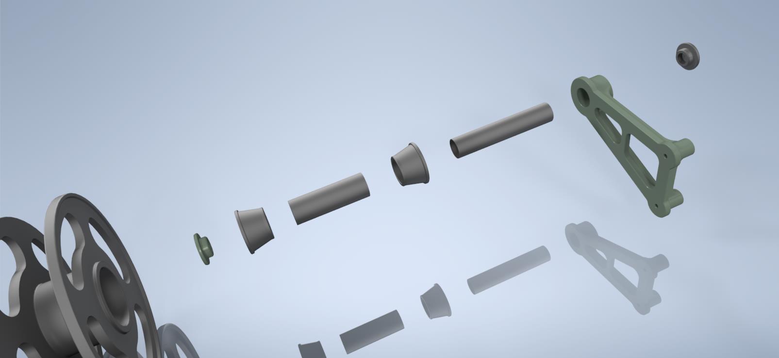
And that’s it.
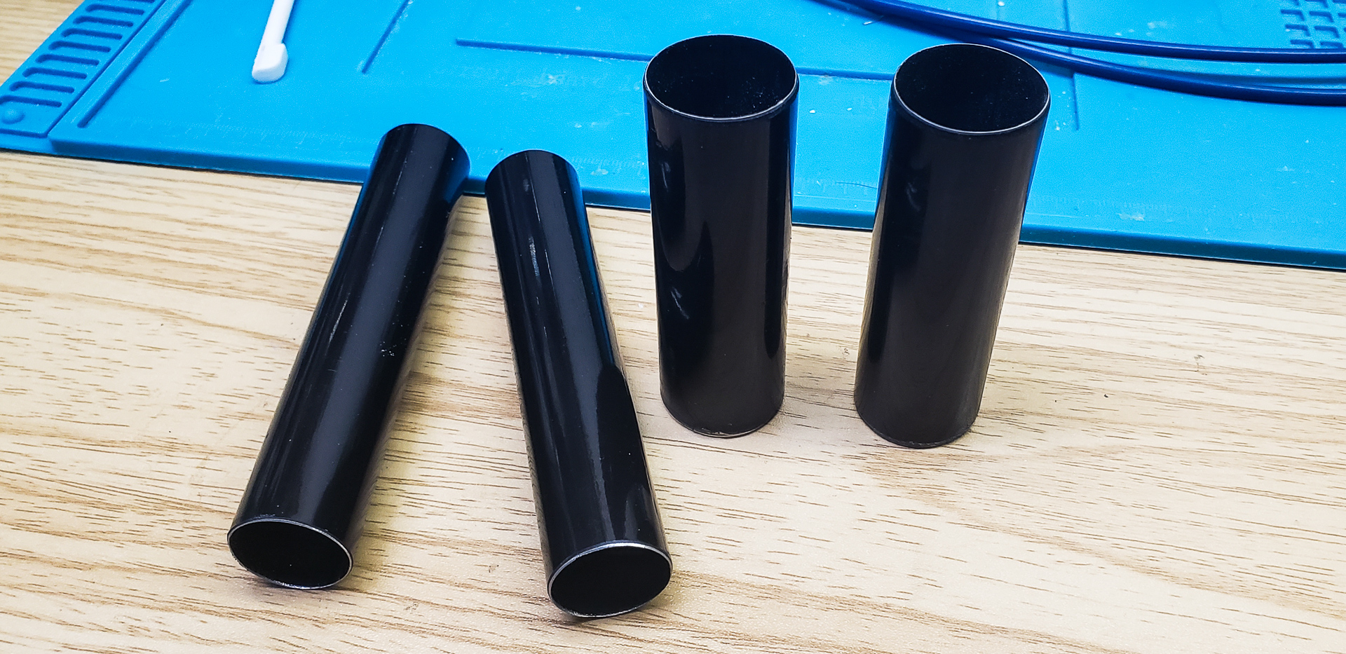
The only tricky part was finding tubes of the right size. But — surprise, surprise! — “by an incredible coincidence,” it turned out that telescopic mop handles could serve as perfect donors for these tubes. Just cut them into pieces of the desired length:
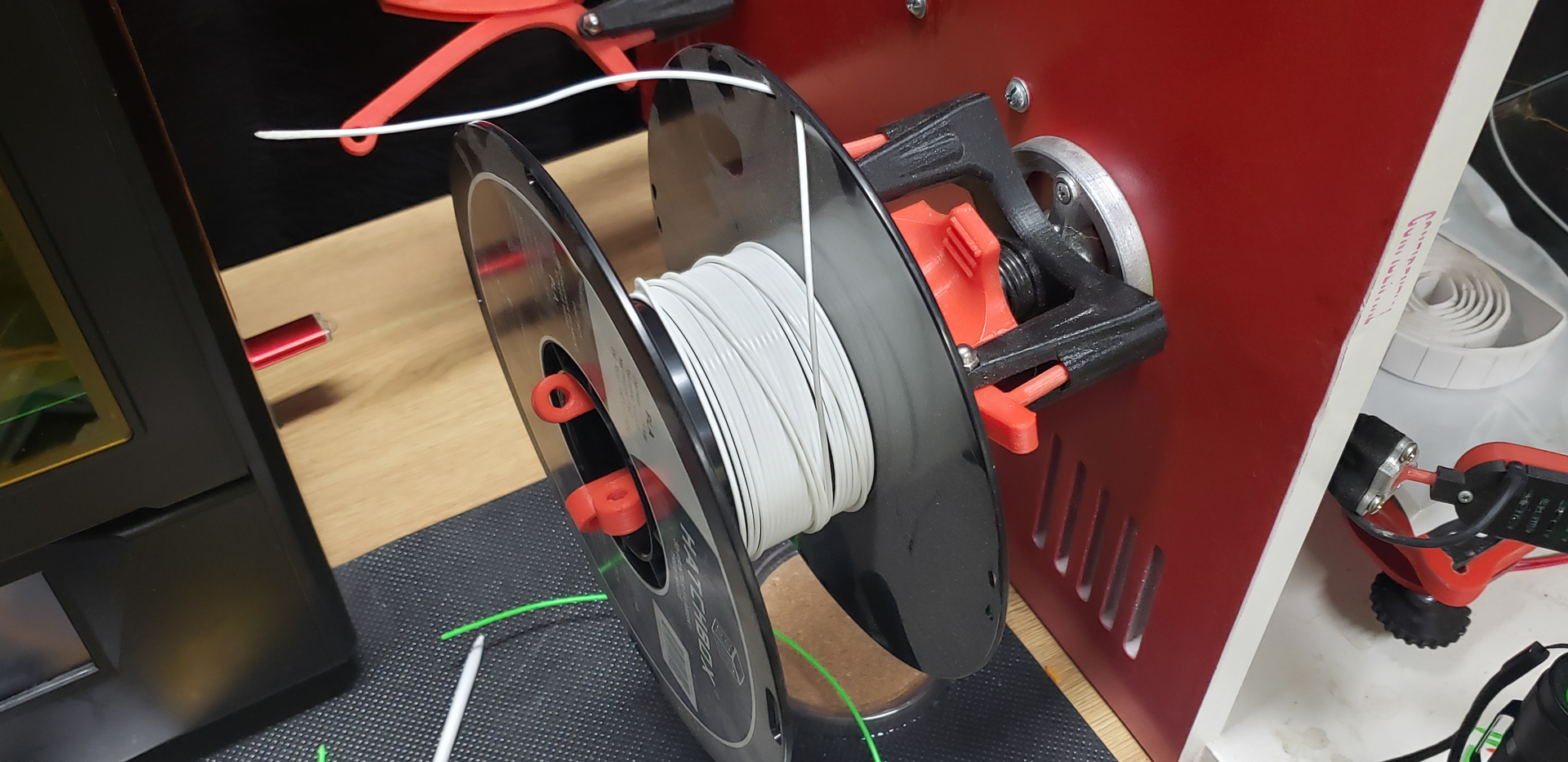
The plastic components of the structure, of course, could already be printed by the Turret itself. It just hadn’t had a place to mount the spools before, which is why it had been stuck feeding off the Widow. But now, finally, the young Turret could be weaned off the old widow and start feeding itself independently:
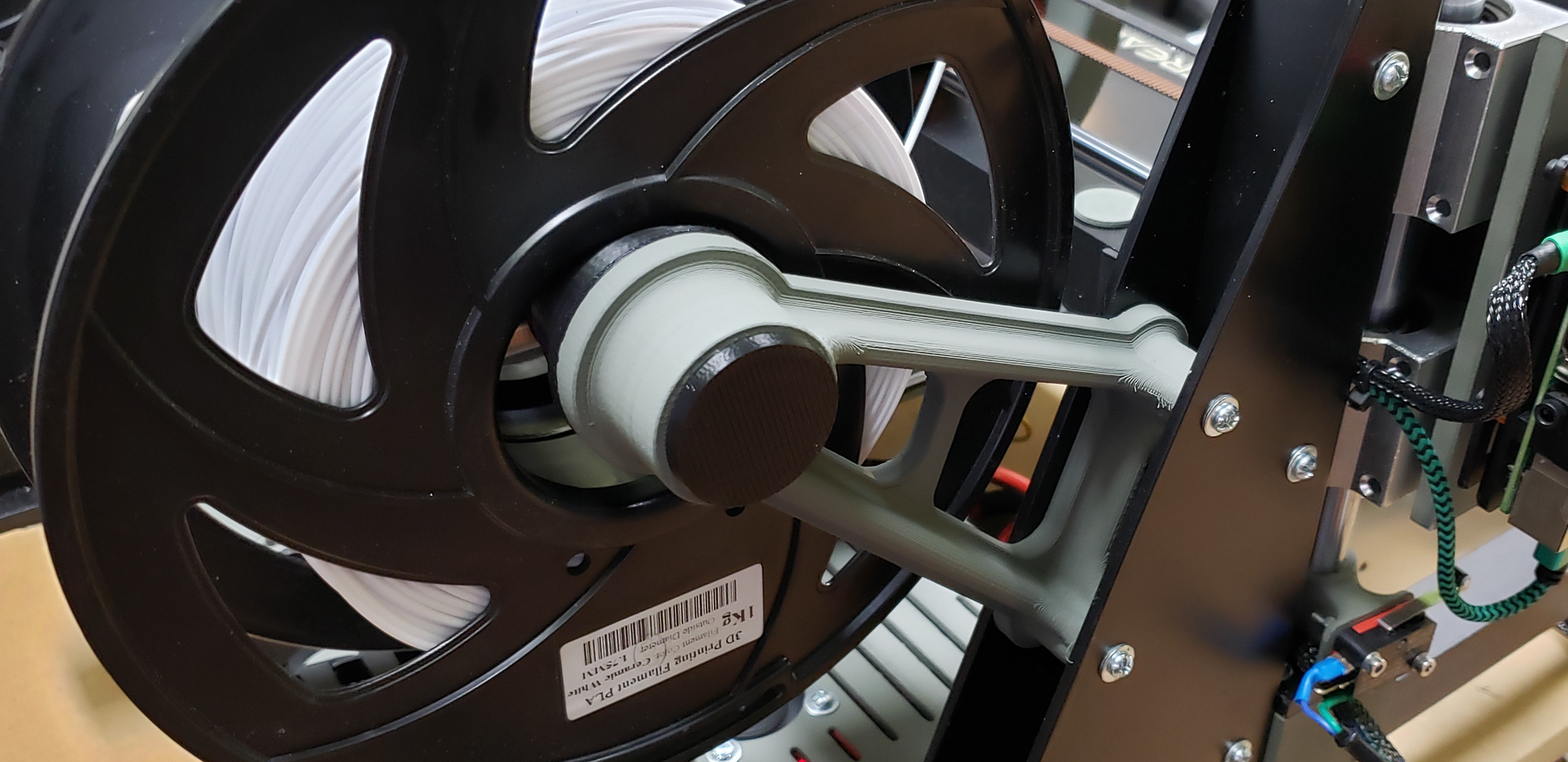
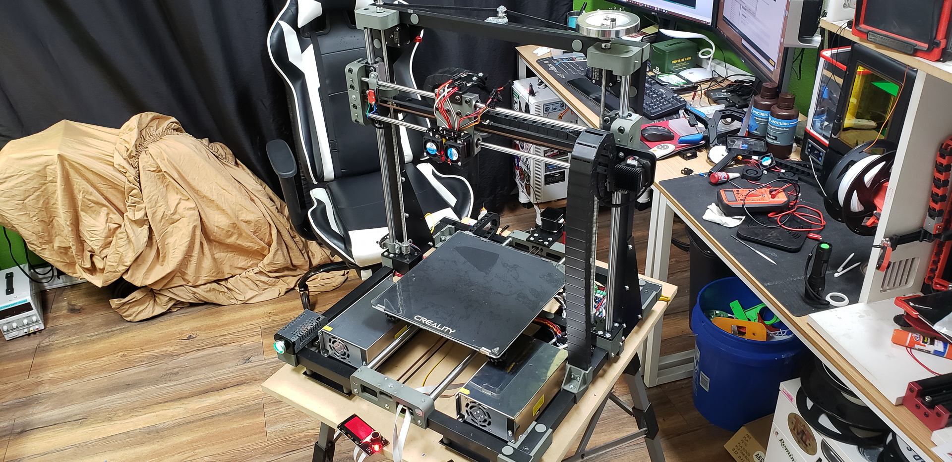
With the spool mounts in place, the Marsh Turret now has an absurdly infernal appearance, like a battle mech straight out of a anime:
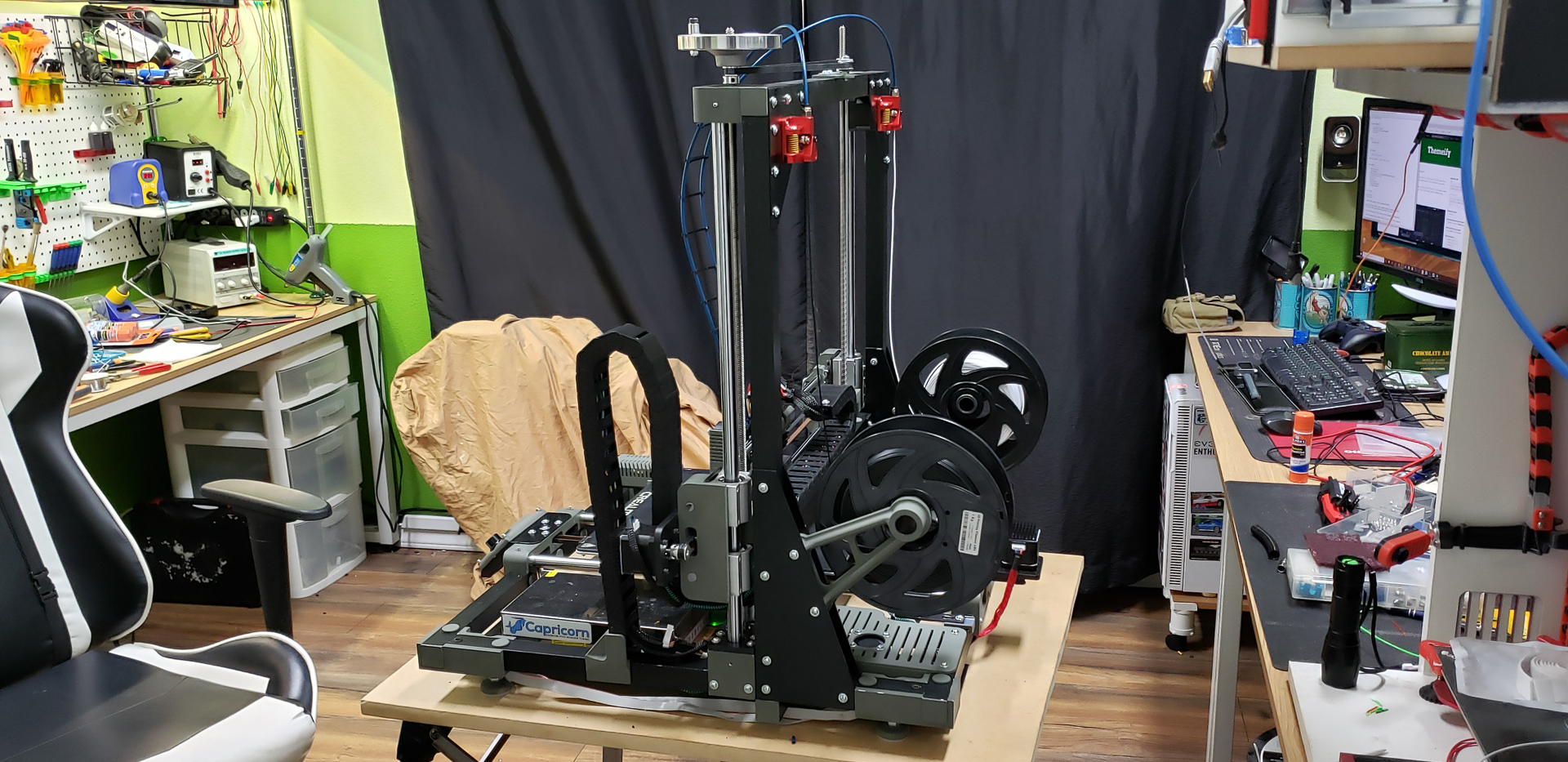
At this point, I’m seriously considering mounting an AR-15 or something similar on it and teaching it to fire a few victory salvos into the air after successfully completing a print. Why not?! The neighbors will get used to it eventually…
The last addition to the print head assembly isn’t so much a functional component as it is an accessory.
The Bowden tubes that feed filament from the extruder to the print head are quite long — 800 mm. This is near the recommended maximum length for such setups. Generally, it’s said that “the shorter, the fewer problems,” but with a powerful extruder and solid mounting, the tube length can stretch to as much as a meter.
My extruder turned out both strong and reliable, and the mounting is rock-solid. However, to further reinforce the setup and lock in the good results, I decided to add something akin to laces connecting the tubes together, much like on a corset. These are placed as high as the tubes allow, ensuring they can still bend freely and follow the movement of the print head at any height during printing.
These “laces” are simple connectors:
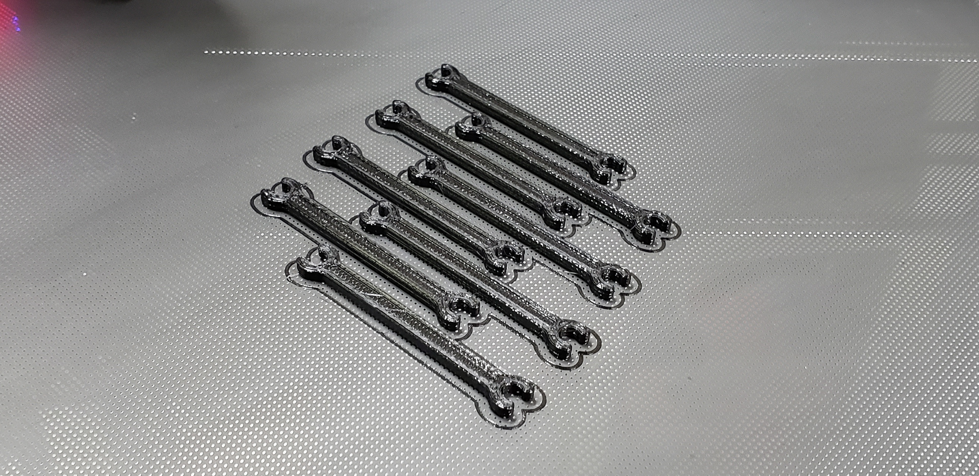
The tubes are joined together with these connectors:
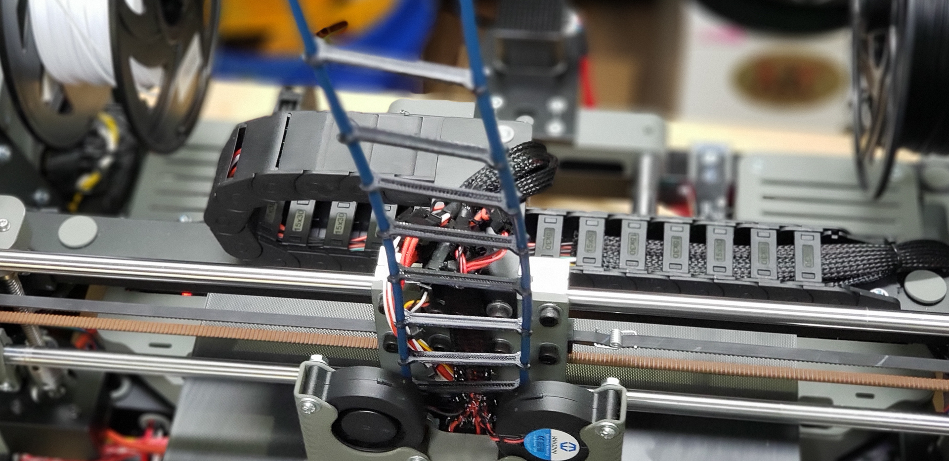
Overall, this setup gives the tubes smoother, more even curves along their entire path. It prevents them from sagging into loops when printing tall models with the print head at its maximum height. Most importantly, it keeps the tubes from snagging on protruding parts of the upper frame. There was one instance where a tube started wrapping itself around the Z-axis handle. With these connectors, such incidents are now completely impossible.
By the time all the components of the print head assembly were in place, work on the printer’s electronics — without which all of this would just be an interesting chunk of metal — was also nearing completion. And that’s what the next part is about.
That’s all for now… To be continued.