
It’s well known that “electronics is the science of connections.” I’ve long noticed that few household or semi-professional electronic devices can illustrate this fundamental truth to a DIY enthusiast as effectively as a 3D printer.
Sometimes it seems as though the entire electronics of this infernal machine consist solely of wires and connections. The basic electronic modules for these types of devices have long been standardized and are available in their finalized form. So, even if you’re building a printer entirely from scratch, connecting the modules is essentially all you’ll have to do. But the scale of entertainment you’ll get from this process will be truly apocalyptic! Of course, this is in the context of traditional home tinkering. If you were to peek inside the “box” of one of our industrial robots, the 3D printer would let out a pitiful sob and go off to dry its tears of envy with its pathetic bundle of wires. Everything in the world is relative…
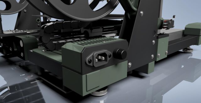
“Theater begins at the coat check” — another fundamental truth. For an electronic device, the “coat check” can be considered its connection point to a power source. In this particular case — the block with the outlet socket and the block with the power switch:

When we first got our hands on serious laser engravers at work, I instantly fell in love with their control interfaces:

I’ve always adored toggle switches and buttons in their classic form from the era before the mass extinction of technical designers in the late 20th century. Nowadays, you only really find them in industrial equipment…
Naturally, about a year or so ago, during a visit to one of the local shops selling second-hand electronics junk, I couldn’t resist saving a button I found sitting forlornly among a pile of modern plastic garbage. I didn’t even know what I’d use it for at the time, but I just couldn’t leave it behind. It was a bit worn, of course, but industrial-grade components last an incredibly long time — this button will likely outlive all of us. Until now, it had been resting quietly in my stash, waiting for its moment in the spotlight. I pulled it out, cleaned it up, and washed it with alcohol — now it looks as good as new:
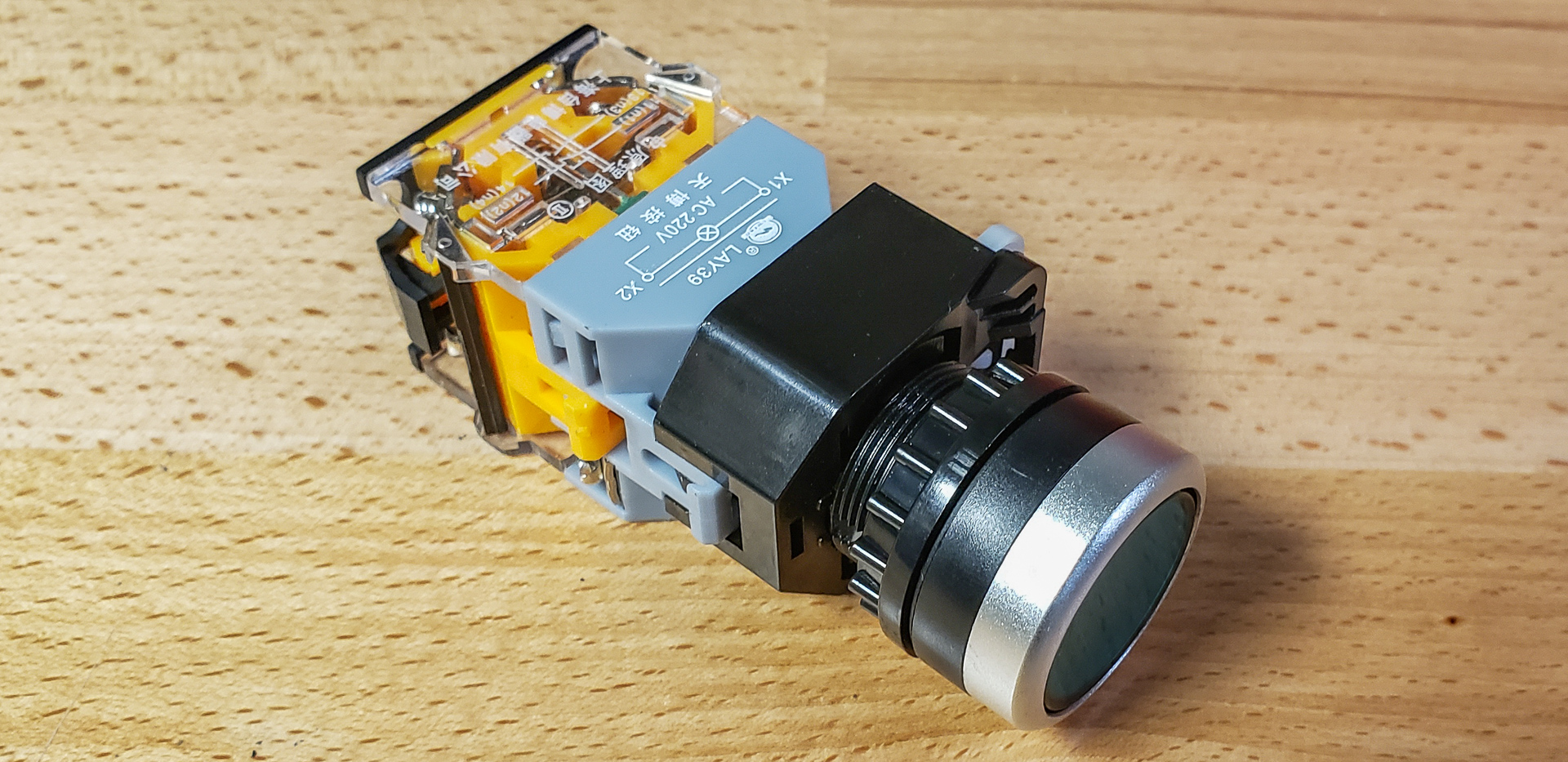
As you can see, I slightly bent the truth earlier when I said that all the components for this project were bought specifically for it, with none taken from my stash. This button, however, is the exception. It’s just too good to pass up. I’ve been waiting a very long time for it to find a truly worthy application…
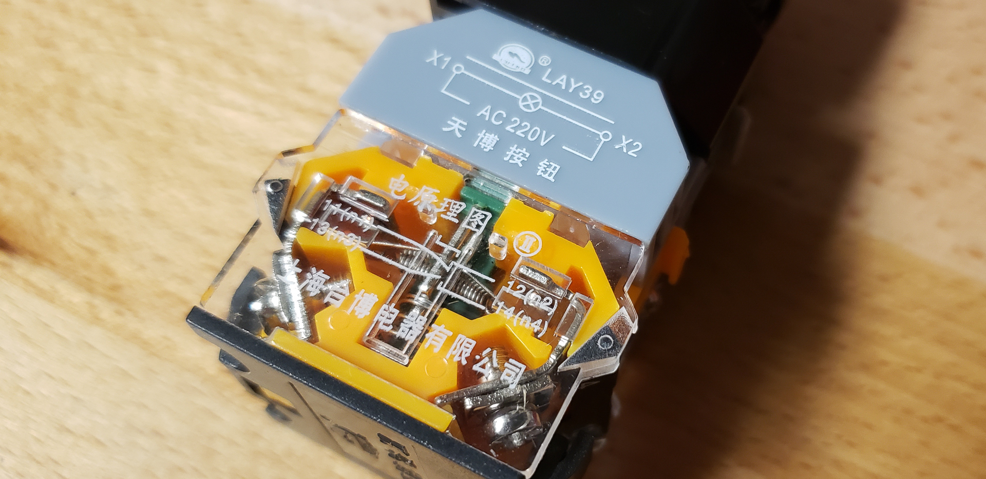
This button is designed to handle high-voltage circuits. It doesn’t just break a single line — it cuts both at once. That is, it simultaneously disconnects both the live and neutral wires. And the best part? There’s a neon lamp inside it. Literally. Not one of those cheap “LED backlit button discount 20% special offer” things. This means it doesn’t require any additional wiring or separate power supply for the illumination. The backlight is powered directly by the same 110 volts from the outlet that the button itself controls.
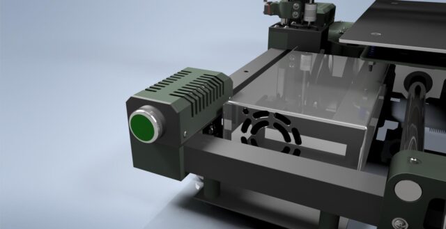
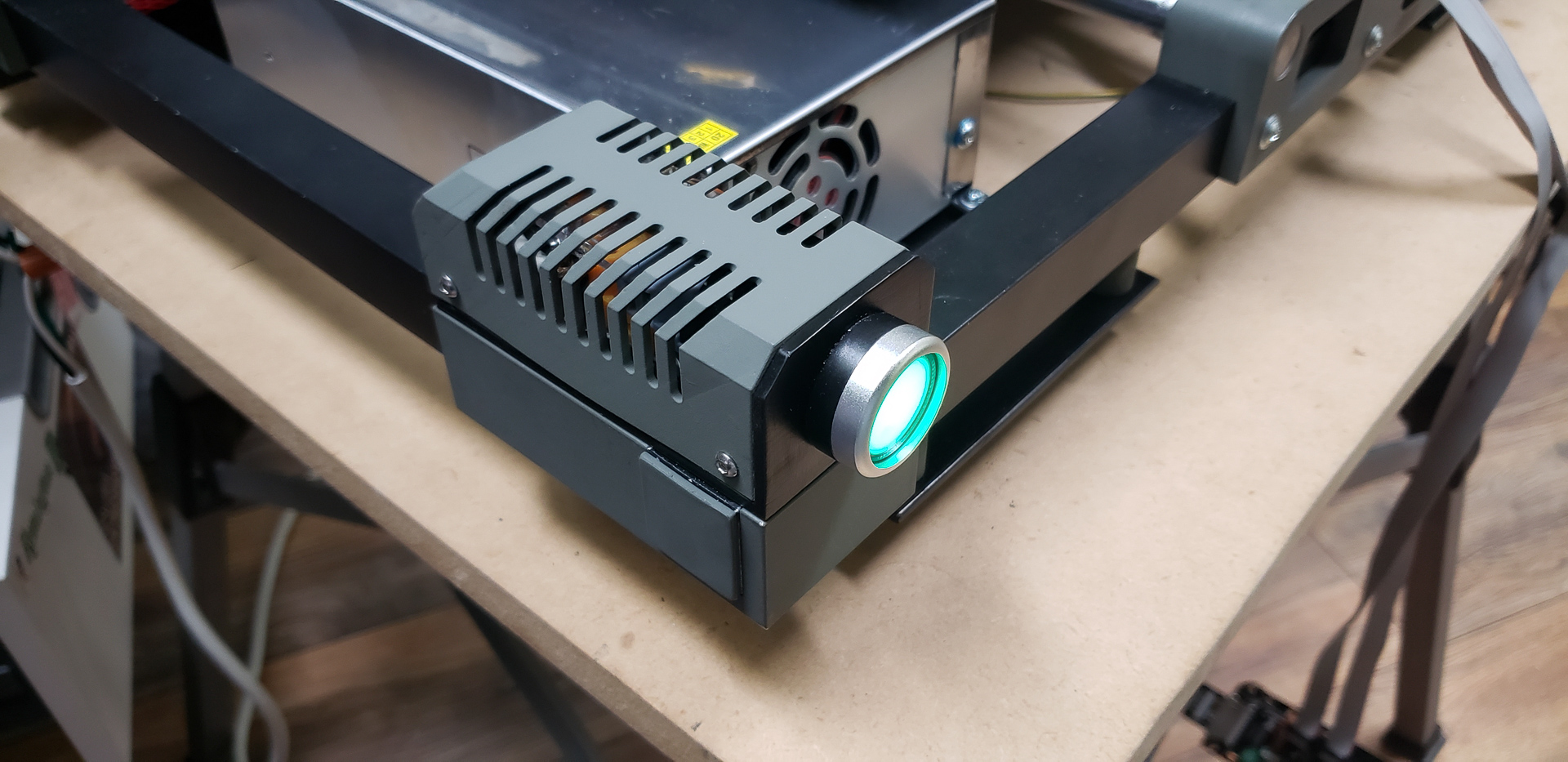
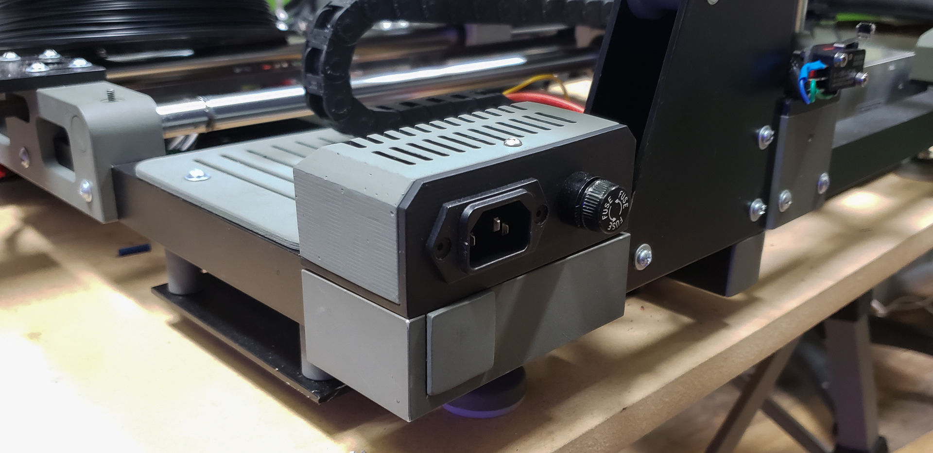
In the printer, the button occupies its own housing on one of the front corners of the frame:
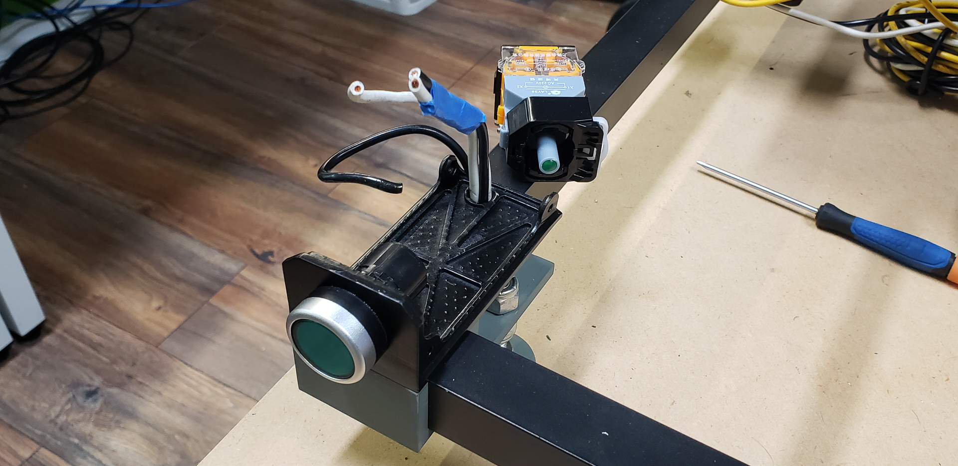

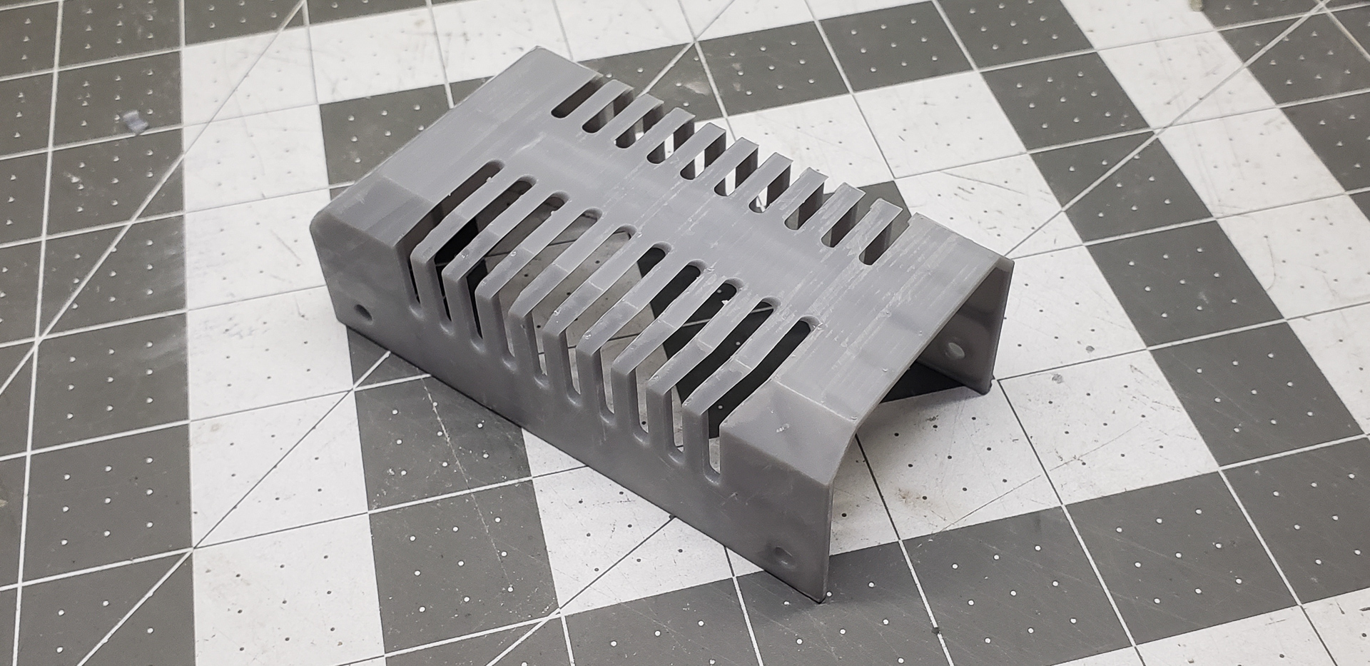
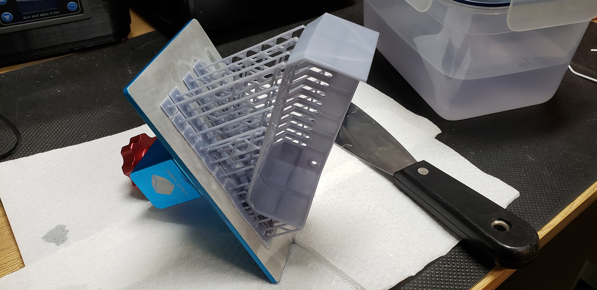
At the time of installation, the printer wasn’t even close to functional — it couldn’t even “meow” on its own. So, the housing parts for the button were printed using a Photon resin printer. Both the base and the cover:
The outlet block was made in a similar fashion:
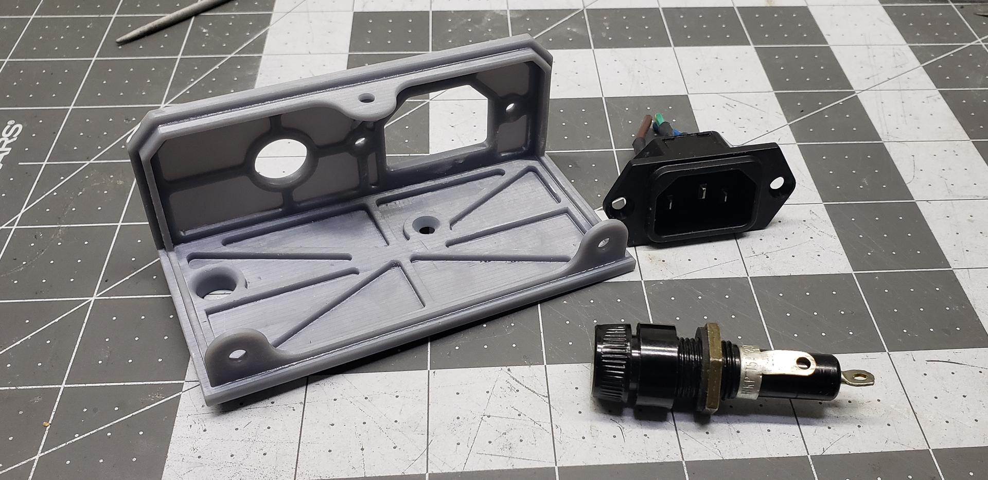
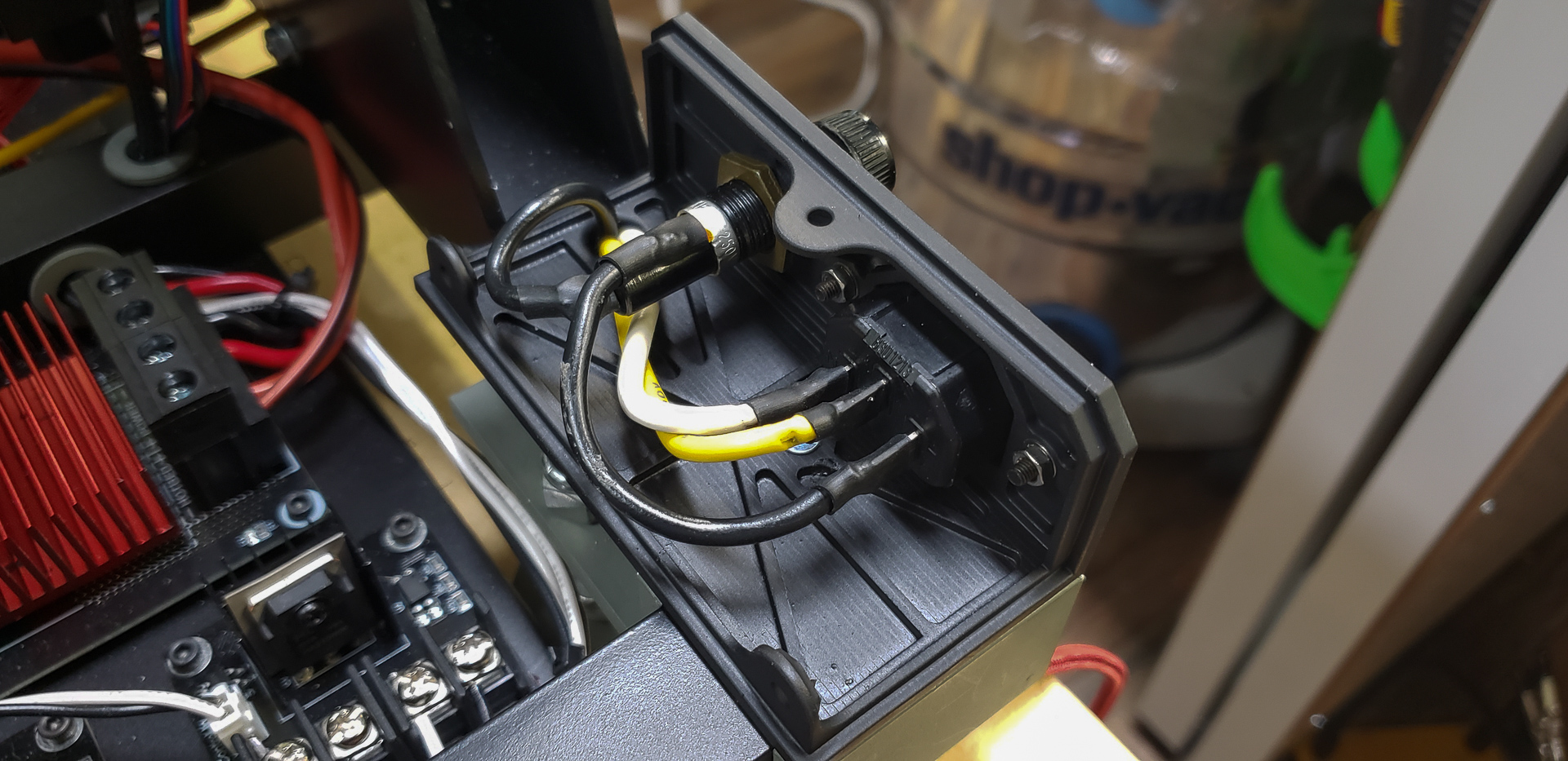

This part is straightforward. It’s just a standard IEC320 C14 “computer” outlet with a simple 15A glass fuse (6x30mm).
When power was finally connected to the printer, it was time to load it up with the rest of its components: power supplies, the controller, MOSFETs, and all the other essential elements.
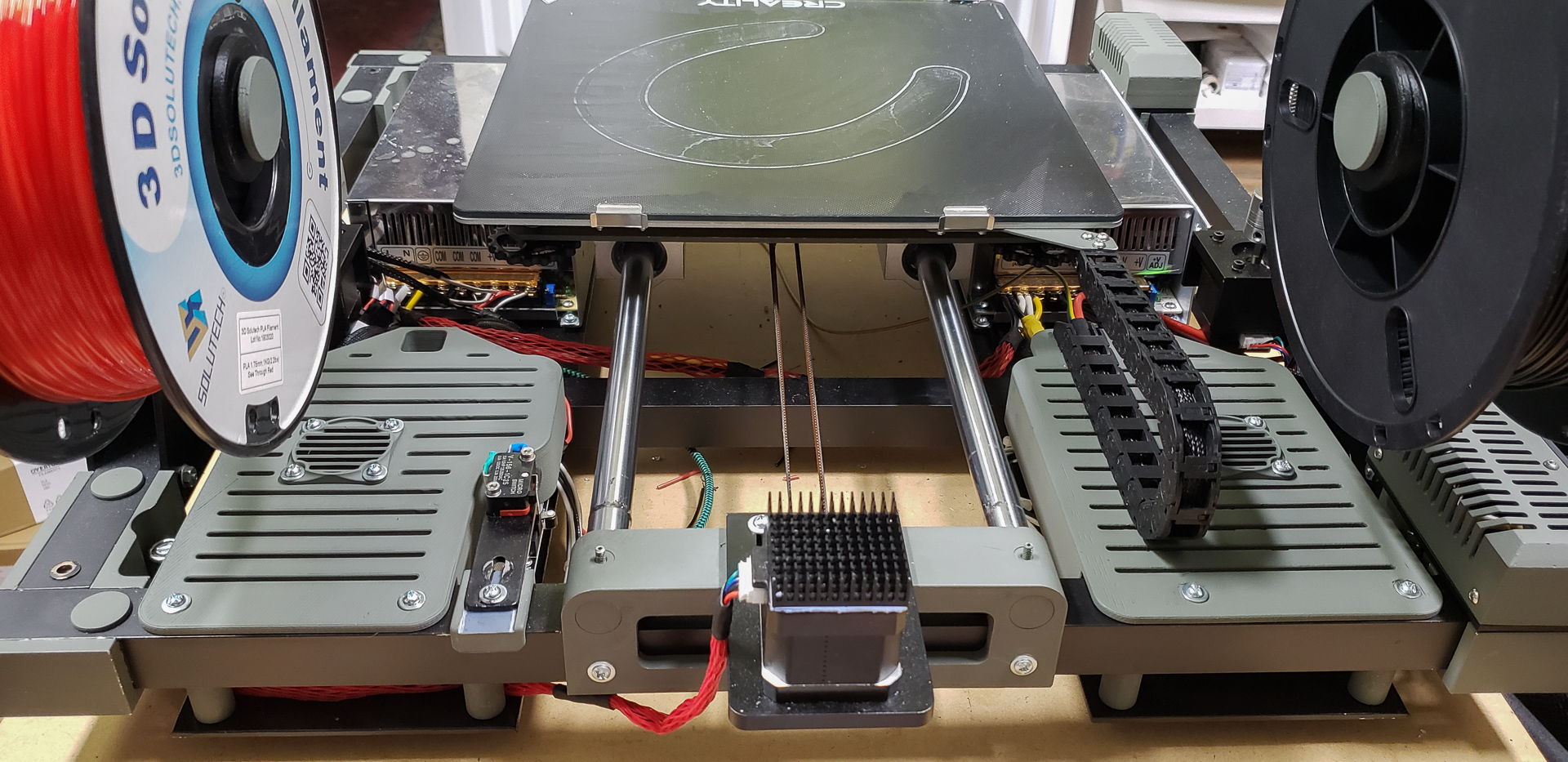
The space designated for housing all the electronics was located under the printer’s workbed. There’s plenty of room there:

Although, as you can see, while there’s generally a lot of space, it wasn’t possible to cram everything into one spot. I had to split the electronics into several groups:

- Power supply for all heating elements
- Power switches (MOSFETs) for controlling the heating elements
- Control electronics
- Power supply for the control electronics
- Display
Yes, this layout results in slightly longer wiring between some components. On the other hand, no matter how you arrange it, the total amount of wiring would remain the same. A few extra inches of length on some wires don’t really make a difference, especially since most branches already measure in feet. What matters is that the entire setup is unified. It’s a complete, self-contained device — “unplug it and carry it away,” with no external power supplies, detached units, or other add-ons.
The foundation for mounting all the internal electronics consists of two large aluminum panels integrated into the printer’s frame:
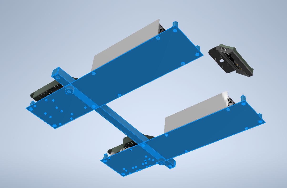
These panels were marked and drilled in advance, before installation:
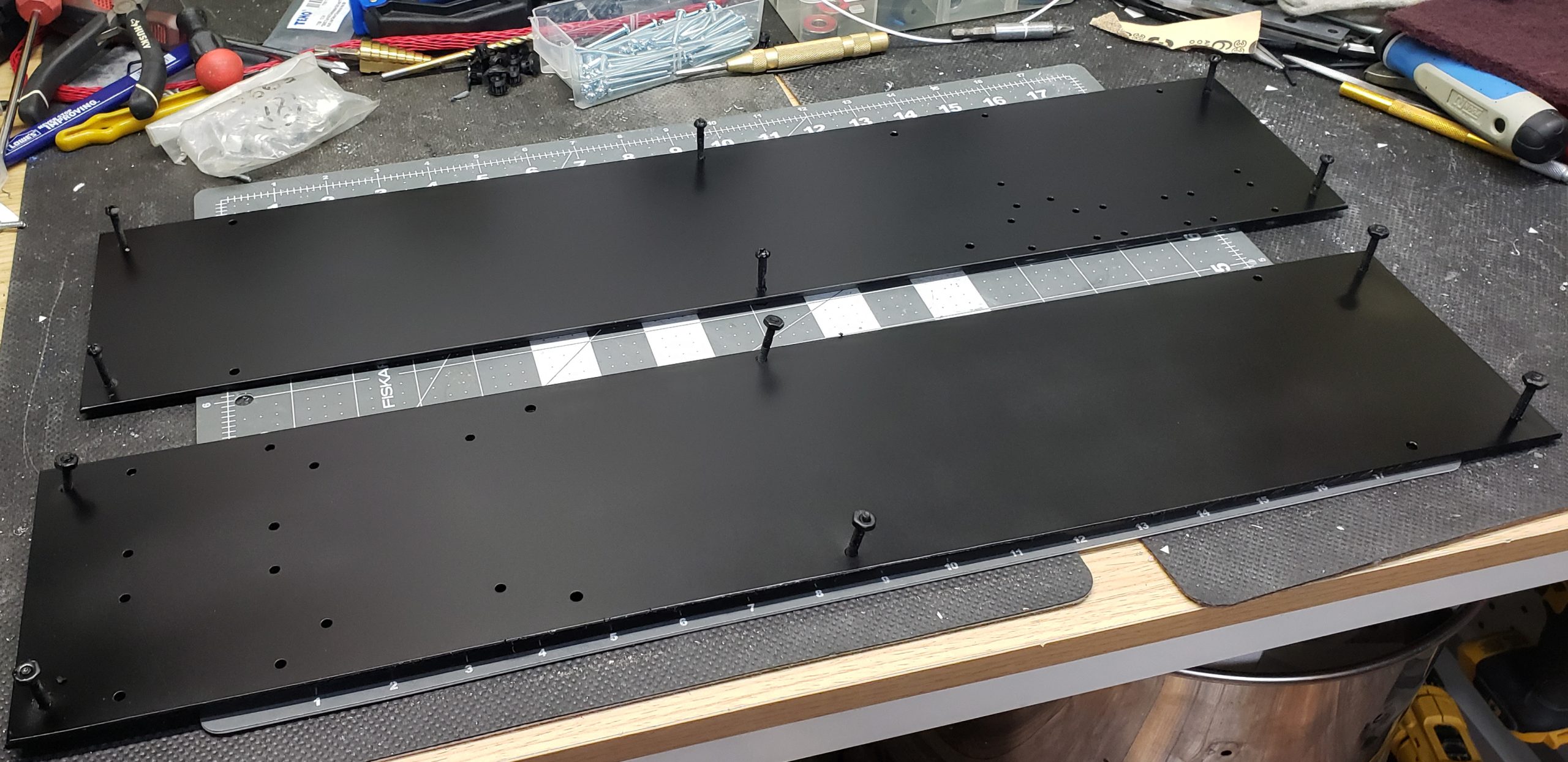
In other words, there was no “on-the-spot drilling” with sudden metal shavings flying over some circuit board. Thanks to standardization, this could all be prepared beforehand, even though some components were still en route in postal trucks at the time.
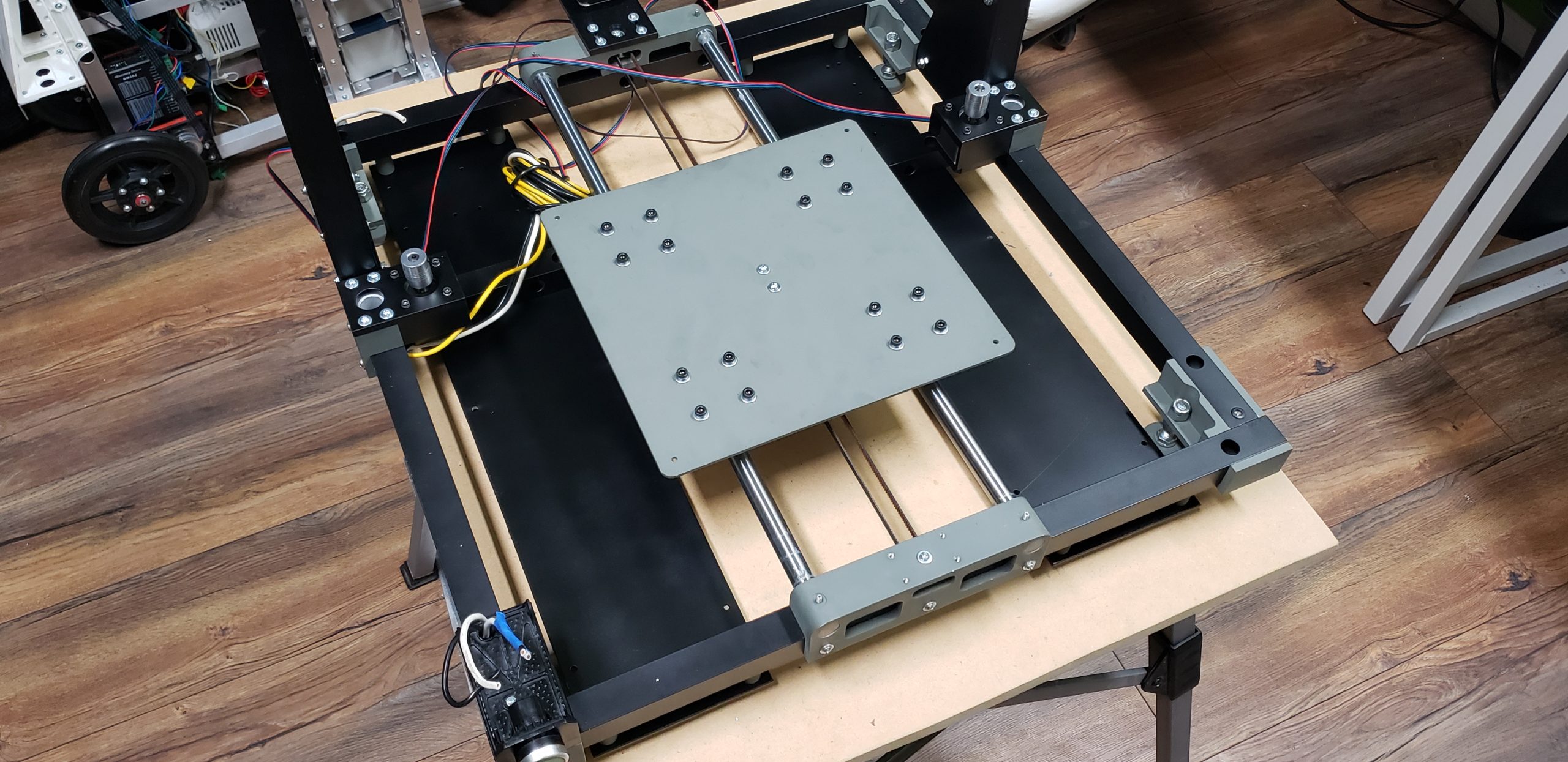
And of course, the printer doesn’t rest its considerable weight directly on these panels. It stands on sturdy legs (originally intended for “garage” shelving and rated to hold much more than the weight of the printer and its “considerable heft”):
So, the panels are essentially suspended beneath the printer’s frame. However, they do have small additional legs of their own, which can be seen in the area around the central crossbeam (the small black ones). These legs are more for reinforcing the U-shaped assembly of the Z-axis, which is mounted right in that section of the frame.
The power supplies for the printer were chosen with a significant safety margin. For example, Black Widow, also a 24-volt printer like Turret, only needed a single 600W power supply, which was more than sufficient.
However, Turret has two print heads, adding an immediate 40W to its power needs. Its heated bed is also more powerful and energy-hungry — 220W compared to Widow’s 160W. Plus, Turret has an additional motor. It’s not a huge load, of course, but an extra 1.5 amps is still an extra 1.5 amps…
By my calculations, a single 600W power supply should have been enough for MARSH TURRET with a 15–20% power reserve — after all, not all components of the printer operate and consume power simultaneously. But, as we all know, everything is made in China. What calculations suggest will give you a 15–20% reserve might, in reality, be more like 5–10%. Or worse, nothing at all. And when that happens, the power supply might release all of its Magic Smoke and stop working entirely.
An 800W or higher power supply would have been a safer choice. Unfortunately, options of that capacity in the same size as a 600W supply either didn’t inspire any confidence or had prices that shot straight into the Constellation of the Toad. So, I arrived at the solution of using two power supplies, splitting their roles, and ensuring a comfortable power reserve for each.
For example, the current setup for the heating elements is as follows: 220W (bed) + 40W (first nozzle) + 40W (second nozzle) = 300W out of 600W. This leaves a 50% power reserve for the heating supply, even when all heaters are running simultaneously. The situation is similar for the second power supply. I can’t overstate how much this simple math improves a DIY enthusiast’s peace of mind during long, multi-day print sessions.
As planned, both power supplies fit perfectly in their designated spots under the workbed:
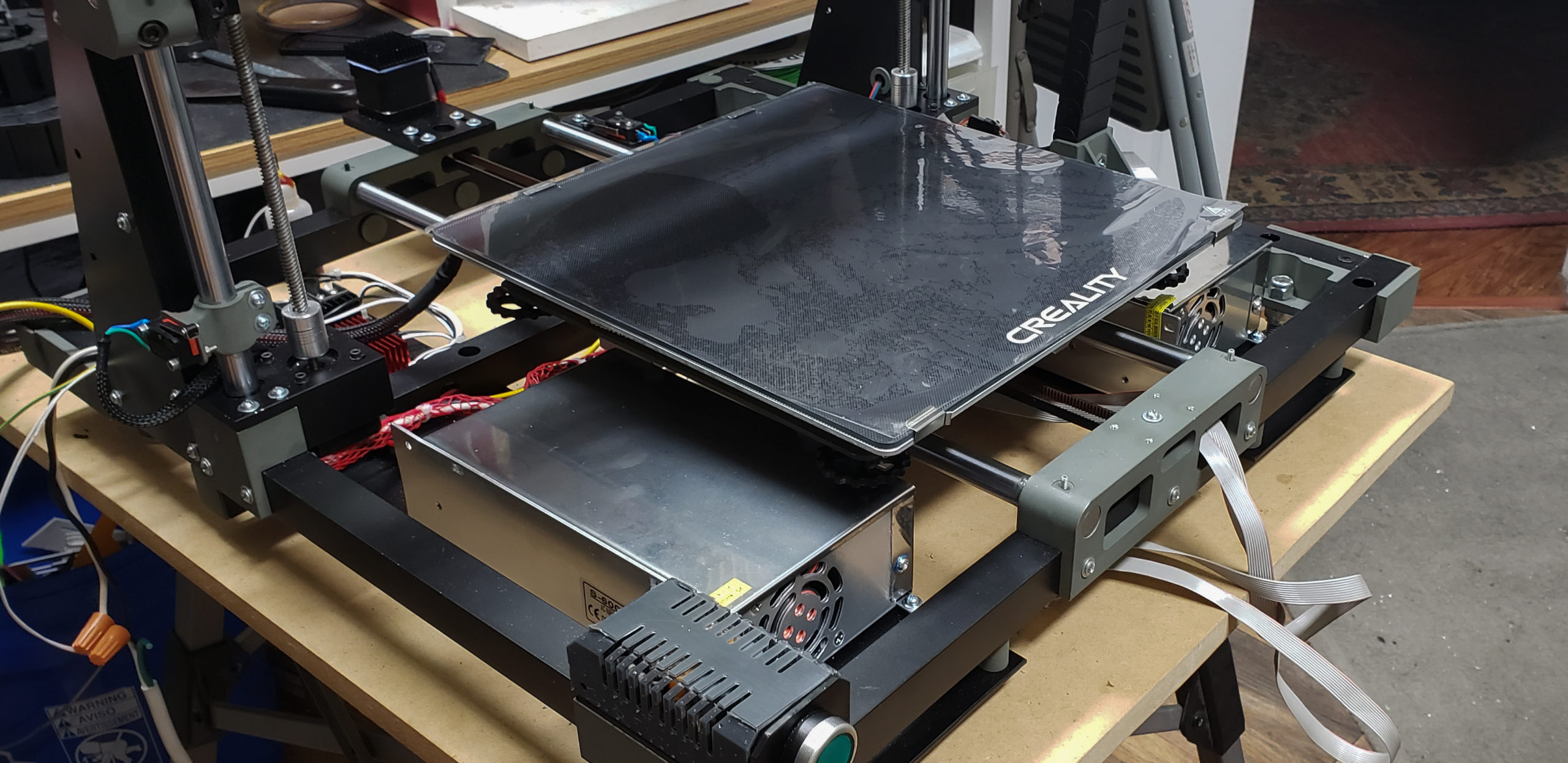
On top of everything else, I really liked the design of these power supply cases. First, no random holes in the walls where debris, screwdrivers, dog drool, or stray fingers could fall through. Air is drawn in through a neat grill at the rear, just above the terminal block (which has an insulating cover), flows through the entire case, and is expelled by a fan at the front. As far as the case and exterior go, there’s absolutely nothing to modify. They are self-contained and perfectly functional as is. Sure, the covers are made from basic thin sheet metal, but the load-bearing walls are solid aluminum.
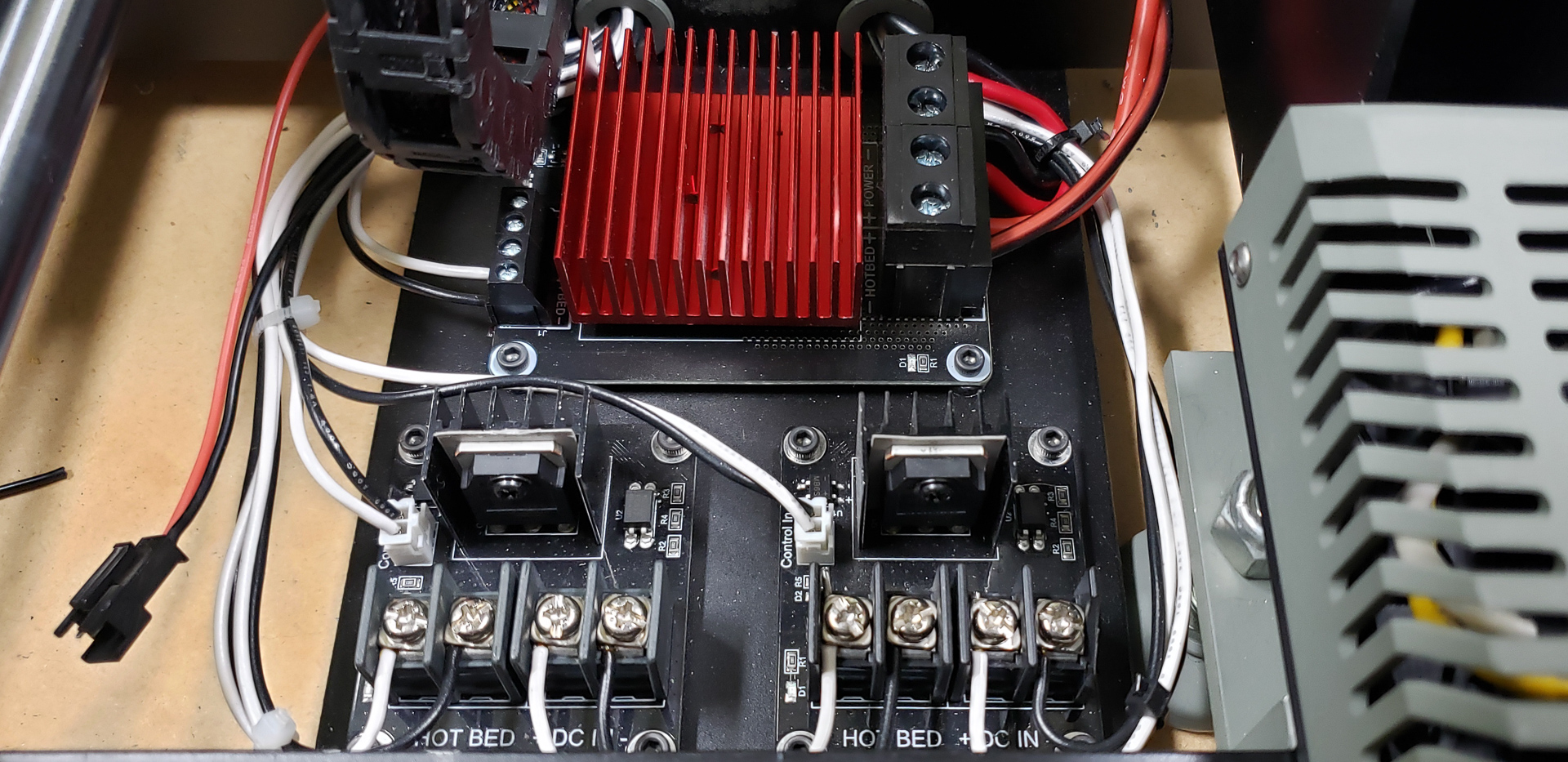
To control the heaters, I used off-the-shelf modules based on MOSFETs:

My Black Widow printer had been running for years with its bed controlled by a module like this one:

I have no idea what specific MOSFET it uses — never cared to check — but these modules are fairly standard and are considered reliable workhorses for controlling heated beds in printers. They’re often referred to simply as “MKS MOSFET,” likely because they were initially developed for Makerbase controller boards. However, nowadays, you can find them in almost any setup, even if the mainboard has nothing to do with MKS. It’s a solid, time-tested option that I trusted for MARSH TURRET’s heated bed.
For controlling the heating elements of the print heads, however, I considered using such a module overkill. Why would they need such a beast? More importantly, three of these bulky modules wouldn’t fit in the designated area of the frame, unless stacked like a sandwich — and that’s a terrible idea.
So, for the print head heaters, I opted for smaller, simpler modules:
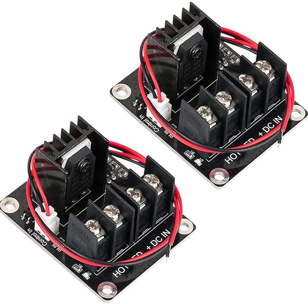
These are supposedly also advertised as being suitable for heated beds. But I seriously doubt they could handle a bed of any reasonable size or power. Sure, they could manage it, but they’d probably heat up as much as the bed itself. However, for the print head heaters, with their modest 40 watts, they’re perfect.
In the end, all three heater control modules found their places:
Since these articles are written retroactively, it’s worth noting that this entire thermal management system has already undergone extensive testing, inspection, multimeter measurements, thermometer checks, Dog sniffs, and Cat stares. It’s been deemed safe, reliable, and fully operational.
Why didn’t I power the print head heaters directly from the controller, as is commonly done? After all, the controller has decent (relatively speaking) MOSFETs of its own. The heated bed, sure — everyone uses an external MOSFET for that. But I haven’t seen many setups that also route print head heaters through external MOSFETs. However, as I mentioned earlier, I was determined from the start to fully separate the power systems for the heaters and the control electronics. Completely. No mixing. Like flies and cutlets. Yin and Yang. Avada and Kedavra. Two power supplies, each powering only its designated group of devices, with no overlap or interconnection. And that’s why.
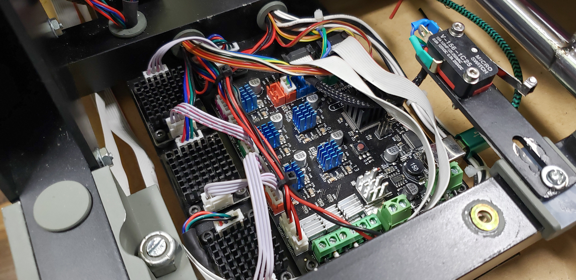
Strangely enough, the group of control modules is the most boring part of the entire printer setup:
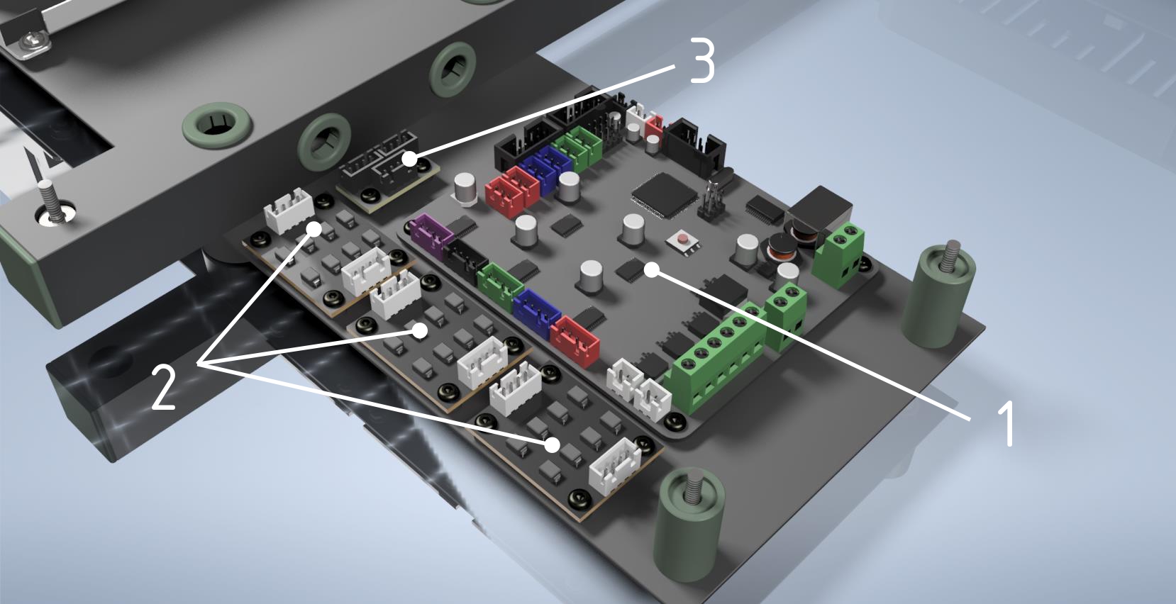
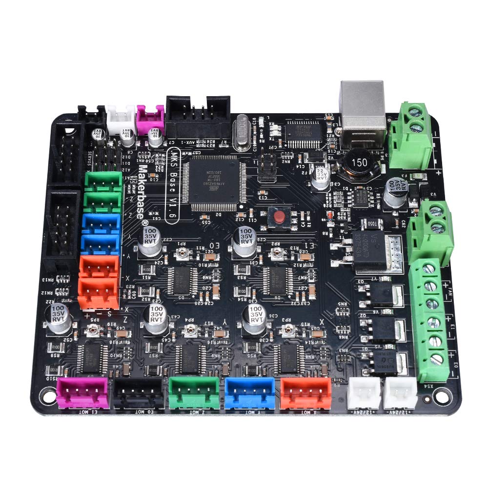
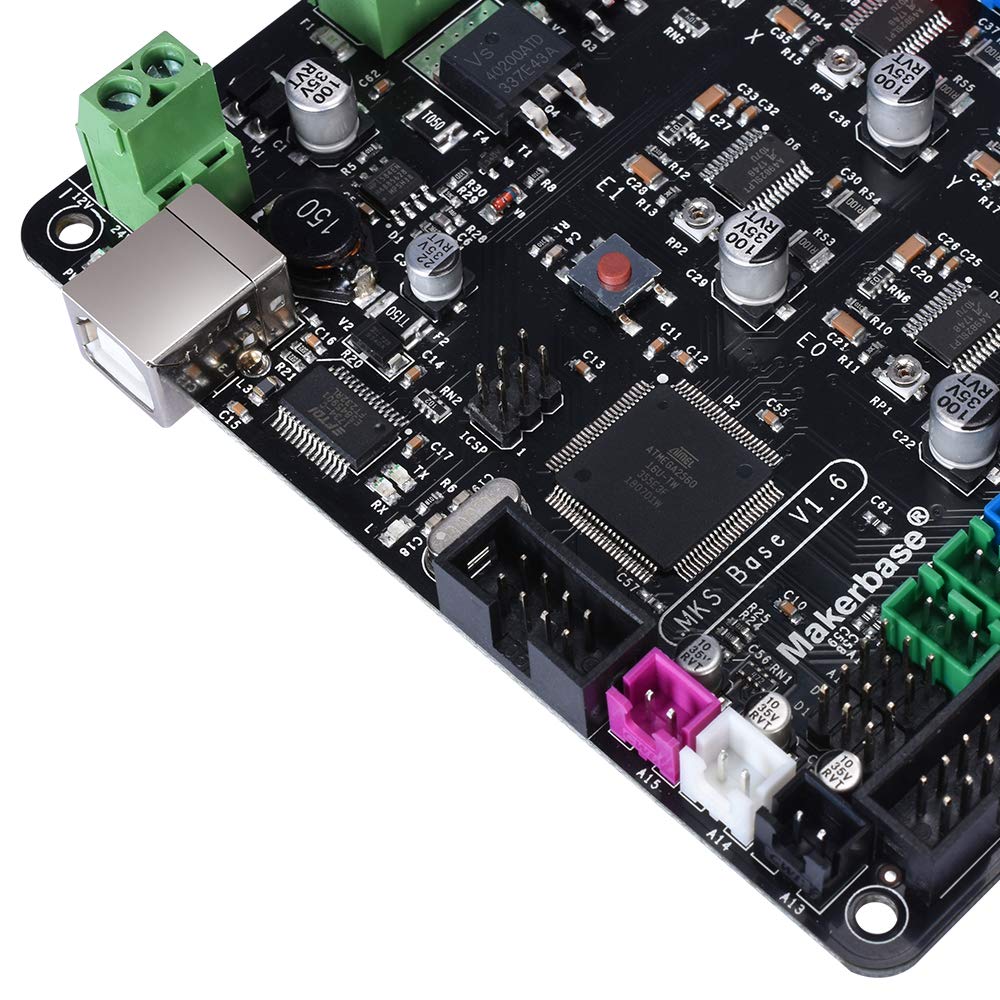
- The central controller: MKS-base v1.6 Ramps 1.4
- TL-smoothers for the motors, one for each axis (Y, Z, X)
- Dual Stepper Motor Module — I have no idea how to adequately translate this into comprehensible Russian. It’s a small board with simple wiring that splits the signals from one stepper motor driver to two stepper motors. I’ll go into more detail about it below.
And that’s it. No need to invent or come up with anything. Everything’s already been invented and designed. All you have to do is put it in place and connect the wires.
About three years ago, I burned out the Widow’s original controller. Essentially, it was the same standard MKS-base Mark-something-or-other from one of the earlier revisions, slightly modified by the manufacturer to suit that specific printer. It was simpler and faster to replace it with a “standard” one. By that time, “standard” controllers had become much more advanced and capable. Over the years, the new controller proved to be incredibly reliable, bug-free, and required absolutely no attention.
Back then, upgrading Widow’s controller was a quick, 30-minute plug-and-play operation. I removed the dead controller, installed the new one, plugged in the connectors, flashed the firmware — done. I even used Widow’s stock firmware, which was essentially a preconfigured version of Marlin. I didn’t have to change a single line of code in the configuration. The only issue was that the mounting holes on the new controller didn’t align with the original mounts. Since I was too lazy to adjust them, the new controller has been hanging off Widow all these years, attached by one screw and a bit of hot glue…
After scouring the internet to see “what’s new since then,” I was disappointed to find that there’s essentially nothing revolutionary. Sure, they’ve been playing with form factors, experimenting with motor drivers, and introducing 32/64-bit processors that are questionably relevant for this field. But fundamentally, nothing groundbreaking has appeared. It’s safe to say that the technology for simple Cartesian printers has reached a stable, finalized form. Over the past couple of years, it’s mostly been about adding gimmicks like “now with Bluetooth and banana flavor!”
So, in this case, I chose not to follow the typical DIY enthusiast path of “something new, untested, and exciting.” Instead, I went the boring route of an industrial equipment designer: “what’s tried, tested, and works well.” I found the exact same controller model from the same manufacturer that I had installed on Widow to replace its original:

However, I had to configure the firmware for it from scratch. By now, a solid second version of Marlin had been released. And, of course, the new printer’s setup was quite different. So, I had to dive deep into the configuration file and meticulously adjust almost everything in it.
Now, onto TL-smoothers — what they are and why they’re necessary.
Bipolar stepper motors, which move the entire printer, are notoriously noisy. Personally, I couldn’t care less about the noise itself. However, that loud whining is merely a symptom of a bigger issue. The motors don’t just produce audible noise — they “scream” electronically, too. The interference they generate in the circuit is enough to make you want to lie down and give up. Currents jump back and forth, inducing, reflecting, and ricocheting off each other — chaos! This affects print quality. The parasitic microvibrations (the ones you can hear) cause visible artifacts on the printed surfaces — “waves,” “ghosting,” “reflections,” and other well-documented defects.
A TL-smoother, placed between the motor and its driver on the controller, is designed to suppress much of this noise and interference. This not only quiets the motor’s operation but also significantly reduces the aforementioned print defects. At its core, it’s an extremely simple filter assembly made up of a bunch of diodes:
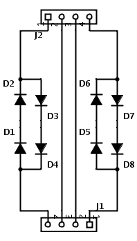
You could easily put one together yourself with whatever components you have lying around. It would work just as well. But as a ready-made module, it’s more convenient and compact:
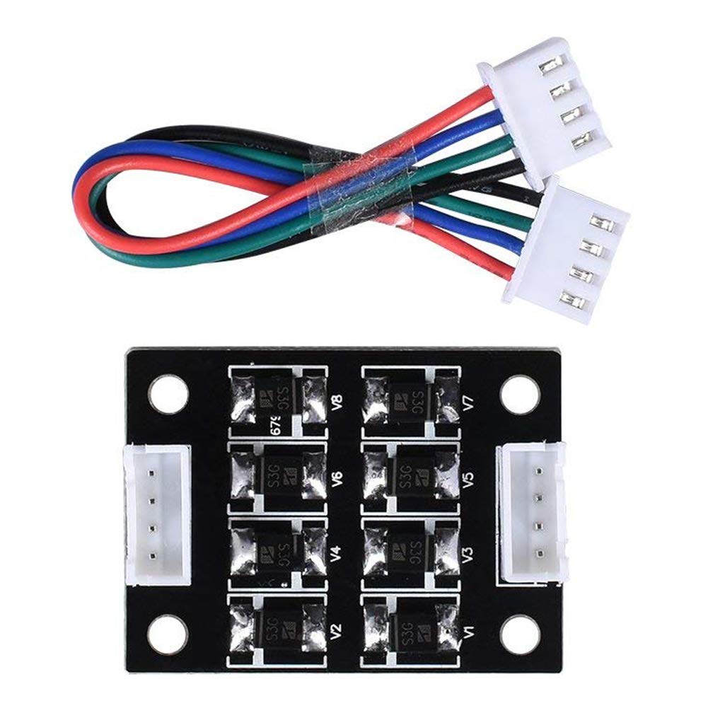
The cost of such a module is negligible — around six to nine dollars for half a dozen of them. However, it’s highly recommended to add a heatsink on top of the SMD diodes because they tend to heat up quite a bit during operation.
Whether TL-smoothers are needed in a printer is a purely personal choice. Many keyboards have been smashed in debates among DIY enthusiasts over this. On one hand, the motor driver on the controller is supposed to handle all this “nonsense” on its own. If it doesn’t, it’s a lousy driver. And I agree with that. However, from personal experience, even with a good “quiet” driver, having this module in the circuit undeniably improves print quality. I’ve had the chance to test this both with Widow’s original controller — equipped with drivers so terrible it’s unclear why they were even there — and with the new controller, which had decent drivers. In both cases, having the TL-smoother in the circuit made a difference you could both hear and see.
For me personally, I’ve decided that TL-smoothers are a must-have in my printer, no matter what controller or motor drivers I use.
And finally, the last component in this group — the Dual Stepper Motor Module:
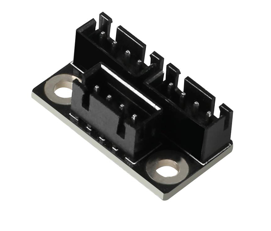
It’s a trivial piece, honestly. Nothing you couldn’t rig up with a soldering iron and some wire. In fact, calling it a “module” feels like a stretch. It’s really just a convenience tool for wiring.
The Z-axis on my printer is powered by two motors working in sync. However, the controller only has one driver and a single output for the Z-axis motor. There are two ways to connect two motors to one driver: wiring their windings either in parallel or in series.
Both options are viable, but each comes with its own caveats. With parallel wiring, you maintain a lower (half of the nominal) but consistent torque at any speed. With series wiring, both motors achieve maximum torque at start and stop, but the torque drops significantly as speed increases.
For a 3D printer, where “better to be steady than strong” is often the guiding principle, parallel wiring tends to be the better choice. If one motor can handle the entire axis on its own, two should manage it just fine, even at half power each. On the other hand, this is the Z-axis we’re talking about, which moves far less frequently than the other axes, and its travel distances are measured in millimeters or fractions thereof. For the Z-axis, the ability to deliver strong bursts of torque at start and stop points becomes more relevant, making series wiring seem more appropriate. But then again… the Z-axis typically uses a leadscrew, whose properties make questions about “start and stop bursts” more theoretical than practical. If the motor drivers on the controller can supply enough power for two motors, why impose limits on Z-axis speed and travel length?
Ultimately, I decided to go with parallel wiring, as it’s the simplest solution. Thankfully, there’s a handy module available for contact routing. If it turns out that parallel wiring doesn’t provide enough power and the driver can’t deliver additional current, I’ll rewire everything in series.
Unfortunately, I couldn’t find any pre-made modules for series wiring, so I’d have to make one myself if needed. Not a particularly complex project — just a board with three connectors and a few traces…
As it turned out, everything worked perfectly in the simple parallel configuration. I didn’t even need to crank up the driver’s output power (though, for safety’s sake, I increased it by 30% above what’s needed for a single motor). At the same time, the driver doesn’t heat up any more than it does when running a single motor (as mentioned earlier, the Z-axis doesn’t operate often or for long). Still, I added heatsinks to all the drivers and set up active cooling for them.
The printer has already been tested in a relatively “long run” (continuous printing for 3.5 days). No overheating, no missed steps, no anomalies of any kind. The Z-axis moves up and down with a speed I’ve never seen before, not even on the Widow. For now, everything stays as it is — the parallel wiring setup works flawlessly.
The Display.
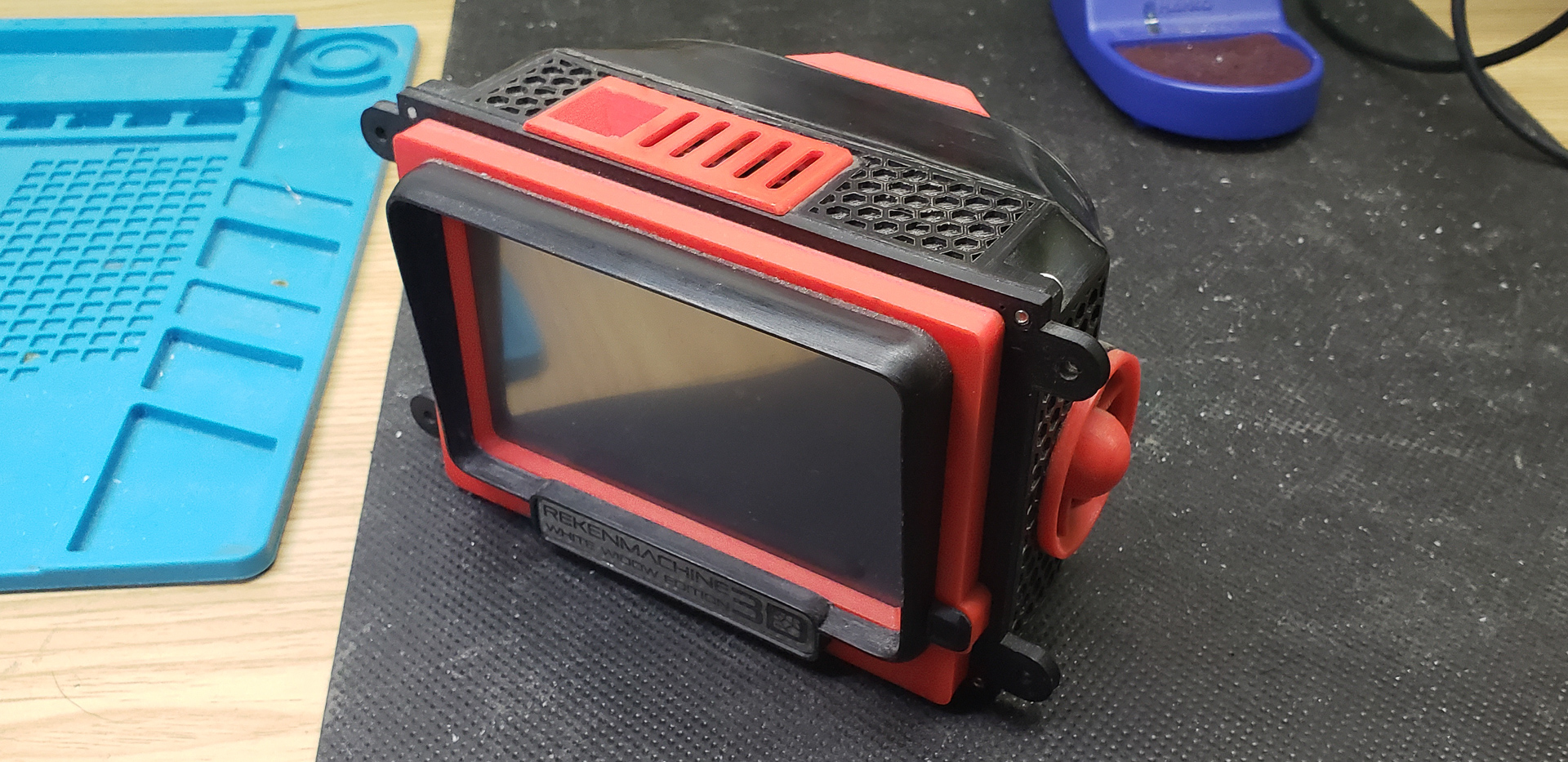
The display is positioned separately from the rest of the control electronics, on the front part of the printer’s frame:

Years of experience have shown that when using a Raspberry Pi with OctoPrint as part of a printer setup, the role of the printer’s onboard display becomes almost negligible. It’s always easier, more convenient, and faster to control and configure printing from a large computer screen with a mouse using an intuitive interface, rather than scrolling endlessly through a million text menus on a tiny printer display. For the same reason, I see no point in having a graphical touchscreen onboard. Even though it’s a bit more advanced, it’s still small, and its interface is never as convenient as an app on a proper computer. Not to mention, such screens cost twice as much and come with so many quirks that configuring the controller firmware to support them could drive you mad.
That said, the printer still needs an onboard display with basic controls, at least as a backup system. If the network goes down or some other issue severs the printer’s connection to the outside world, the onboard Raspberry Pi with OctoPrint becomes useless. And, let’s be honest, having a dedicated display on the printer simply looks cool.
This “coolness” was my guiding principle. Touchscreen color graphical displays don’t fit my highly unconventional sense of aesthetics. They’re instantly disqualified without discussion. That leaves the standard “pixel” LCDs. However, most of them are just plain ugly, especially those horrid blue-backlit rectangles that are considered “standard.”
Fortunately, persistence paid off, and I stumbled upon a very charming display from the Mini12864 series:
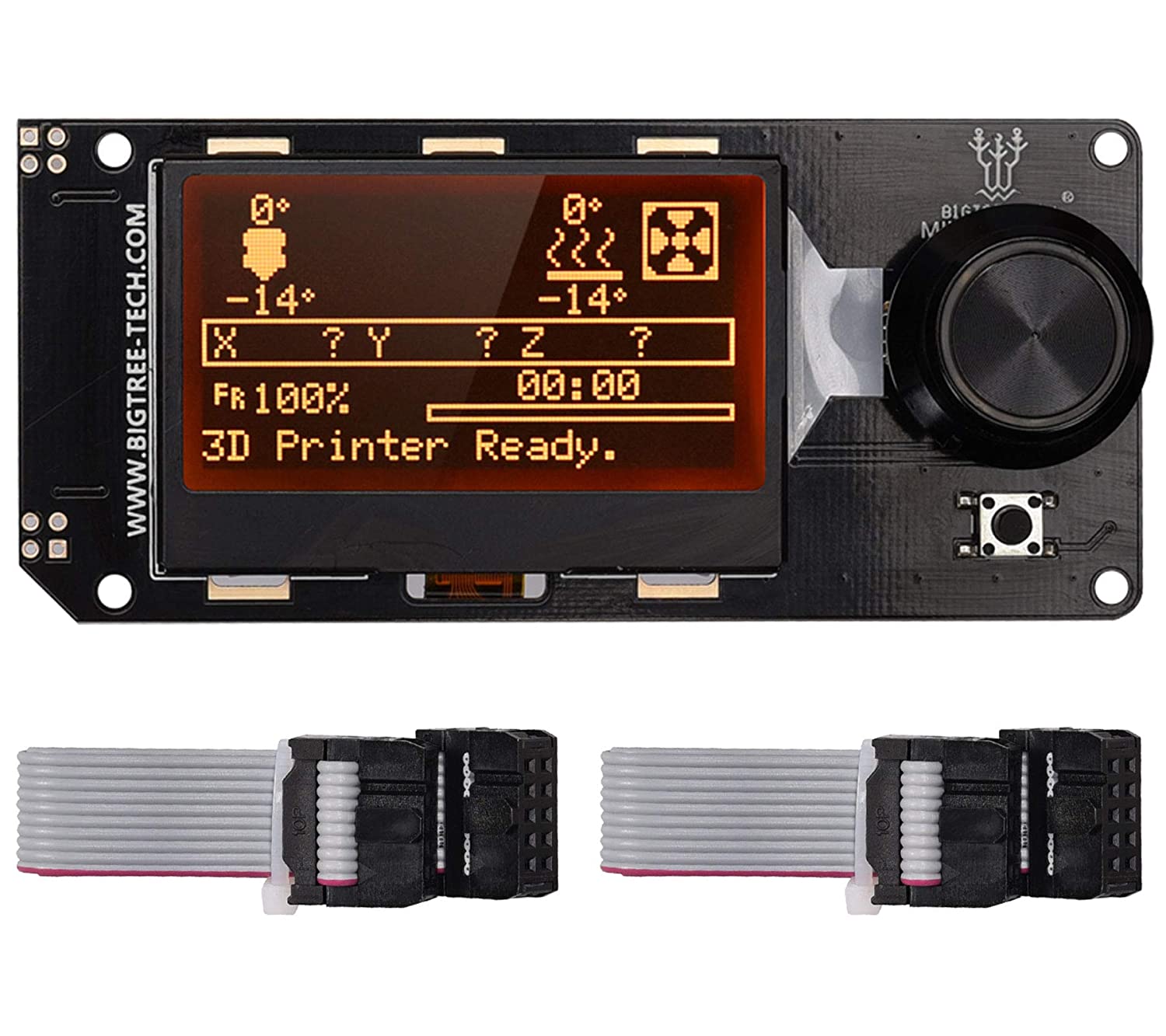
It’s smaller than the typical displays for printers of this type, but that’s perfect for a backup control element. The rotary encoder is on the side, not underneath the screen like on “standard” displays (which used to drive me nuts!). Plus, it has RGB backlighting for both the screen and the rotary encoder, allowing for color customization to suit any twisted taste… or so I thought.
In reality — yes and no. Well, yes… but also no. More precisely, yes, it’s RGB backlighting, and you can configure it. But no, because you might not want to. If you connect this specific display (or a compatible model) and enable it in Marlin firmware, the default behavior is to have the display’s backlighting change color according to the printer’s current operation. For example:
- Red for heating the bed or the print heads (orange for the print heads, with the color shade shifting as the target temperature is approached).
- Gray during preparation (e.g., homing or probing the bed).
- Amber during printing.
- Green when printing is complete.
And honestly, I liked this much more than a static, manually chosen color “to suit my taste.” I decided not to change anything in the configuration. I left all the backlighting settings as they were in the firmware. This kind of dynamic indication is far more intuitive than any text could ever be. A quick glance at the display is enough to understand what the printer is currently doing and why it hasn’t started printing yet.
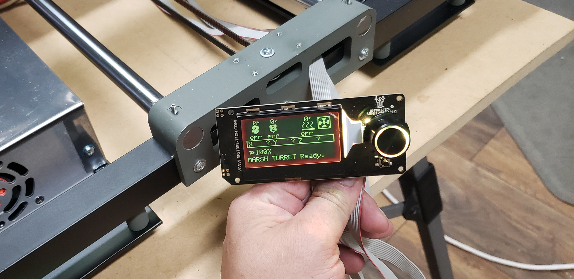

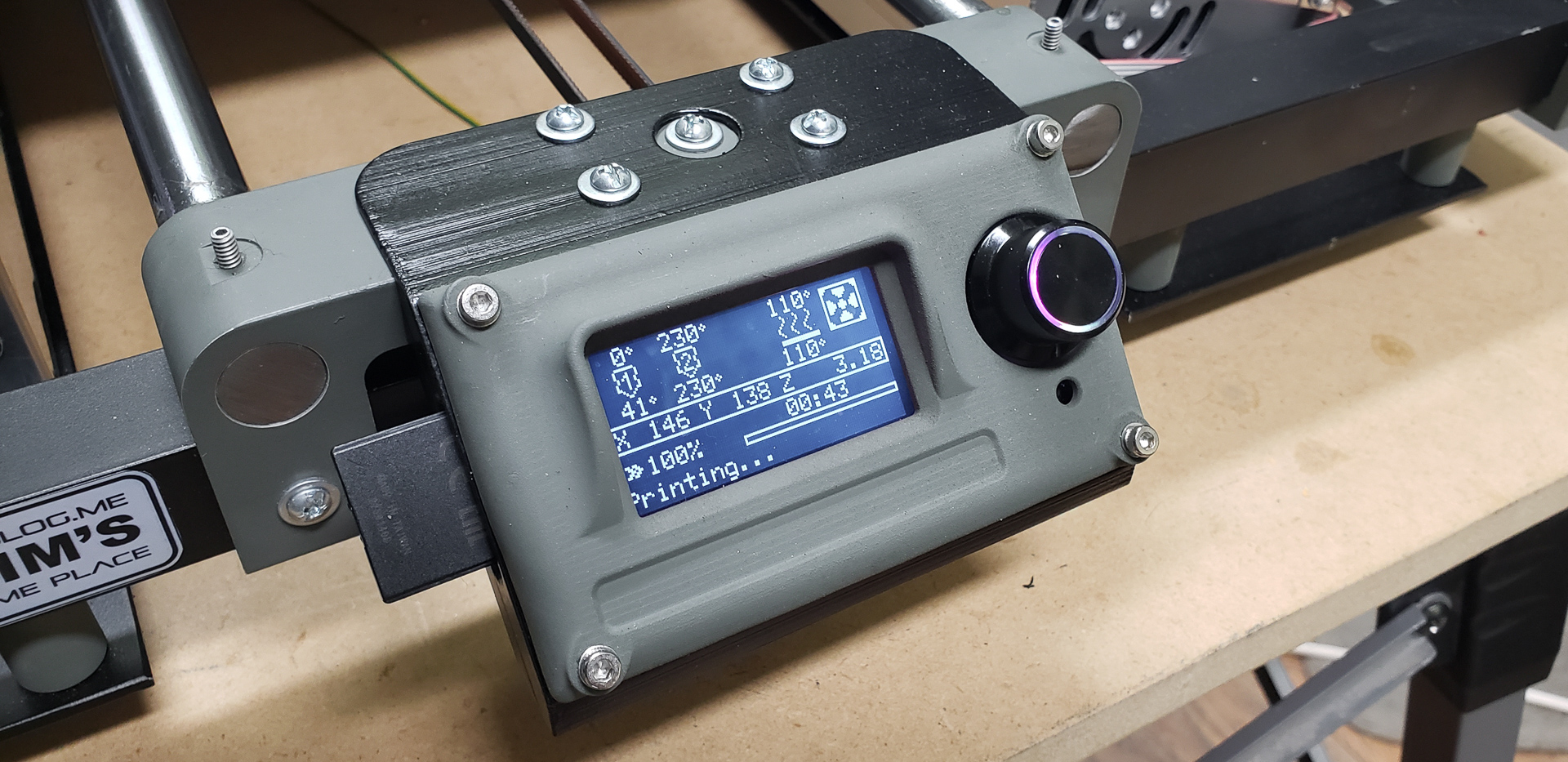

A sleek, unobtrusive display that has been officially recognized as a fantastic choice for my MARSH TURRET…
The display has also been certified by the Cat. Unlike the Dog, the Cat’s color perception is perfectly fine. He sat and stared at it for several minutes, watching the colors shift. At one point, he even pawed at the rotary encoder. He left with a very satisfied look on his face.
There’s one more set of components I forgot to mention in the previous articles of this series. While these components belong to the electronics, they are still an integral part of the printer’s axes rather than the overall system. So, I should have written about them earlier. But here we are…
Endstops, or limit switches — I’ll call them “endstops” for simplicity:

Printers need these to determine the zero coordinate, the reference point from which all printing will be based. For printers of this type, it’s customary to set the origin point here, in this corner of the bed:
The printer itself doesn’t care where the origin is. Humans, however, decided it should be here.
You may encounter printers where the origin is at the center of the bed or the far left corner, but this is rare. Such setups are usually dictated by technical features of the machine, where there’s no other viable option.
The printer doesn’t mind where it starts counting coordinates, but it must know exactly where to begin. It can figure this out in one of two ways: either a human tells it, or it tries to find an extreme position by itself and assumes that as the origin.
Humans — lazy meatbags that we are — don’t enjoy manually setting the printer to its zero position every time. We’d rather let the poor robot do that job for us. And that’s where endstops come in. The robot moves one axis until it hits an endstop. When the endstop is triggered, the robot considers that point as the zero position for that axis. Then it moves another axis until it triggers its endstop… and so on for all axes.
Endstops themselves come in different types. They can be mechanical and contact-based, or “sensor-based” and non-contact. My Widow had the latter. They were absolutely dreadful! If you accidentally nudged them even slightly — just a hair’s width — they’d stop working. Worse still, if a magnetized screwdriver happened to be lying nearby, the sensor would fail to detect proximity and wouldn’t trigger. I’ve lost count of how many teeth were stripped off the belts because of that nonsense. This time, I decided: no sensors, absolutely not. Old-school, reliable “lever microswitches” — as the forefathers intended. And industrial-grade ones at that, built to last! Tough enough to chop firewood with or to use on space shuttles.
V-166-1C25:

I got the idea from one of our workplace CNC mills during a maintenance session. These exact switches were used there. I’m not sure if they’re standard for all parts of the machine, but they’re definitely installed on the tool carousel.
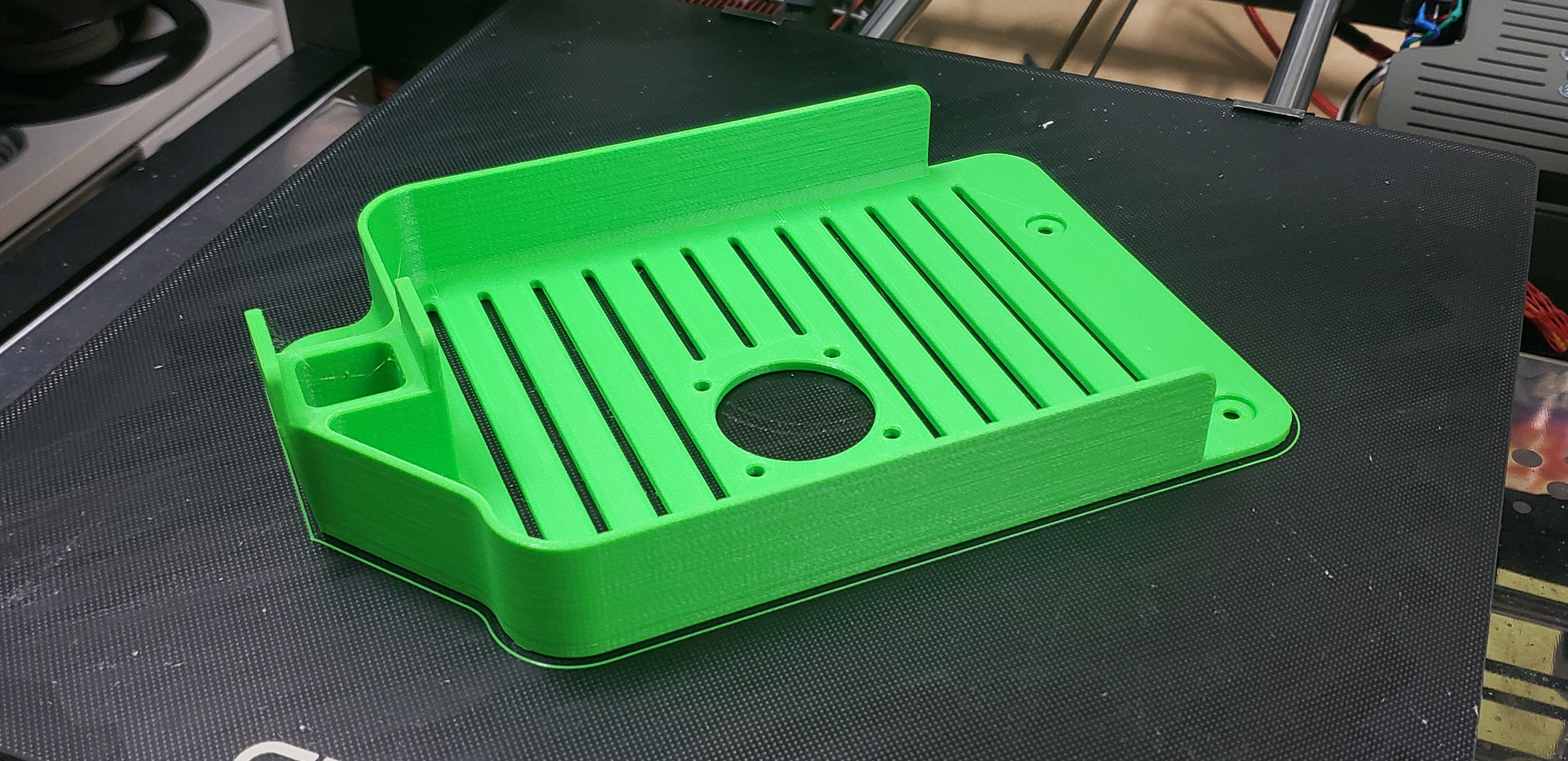
For the Y-axis, installing the endstop was the simplest task. An adjustable aluminum plate was mounted on the frame, and the endstop was attached to it. It sits in place, waiting for the bearing block of the bed to bump into it:
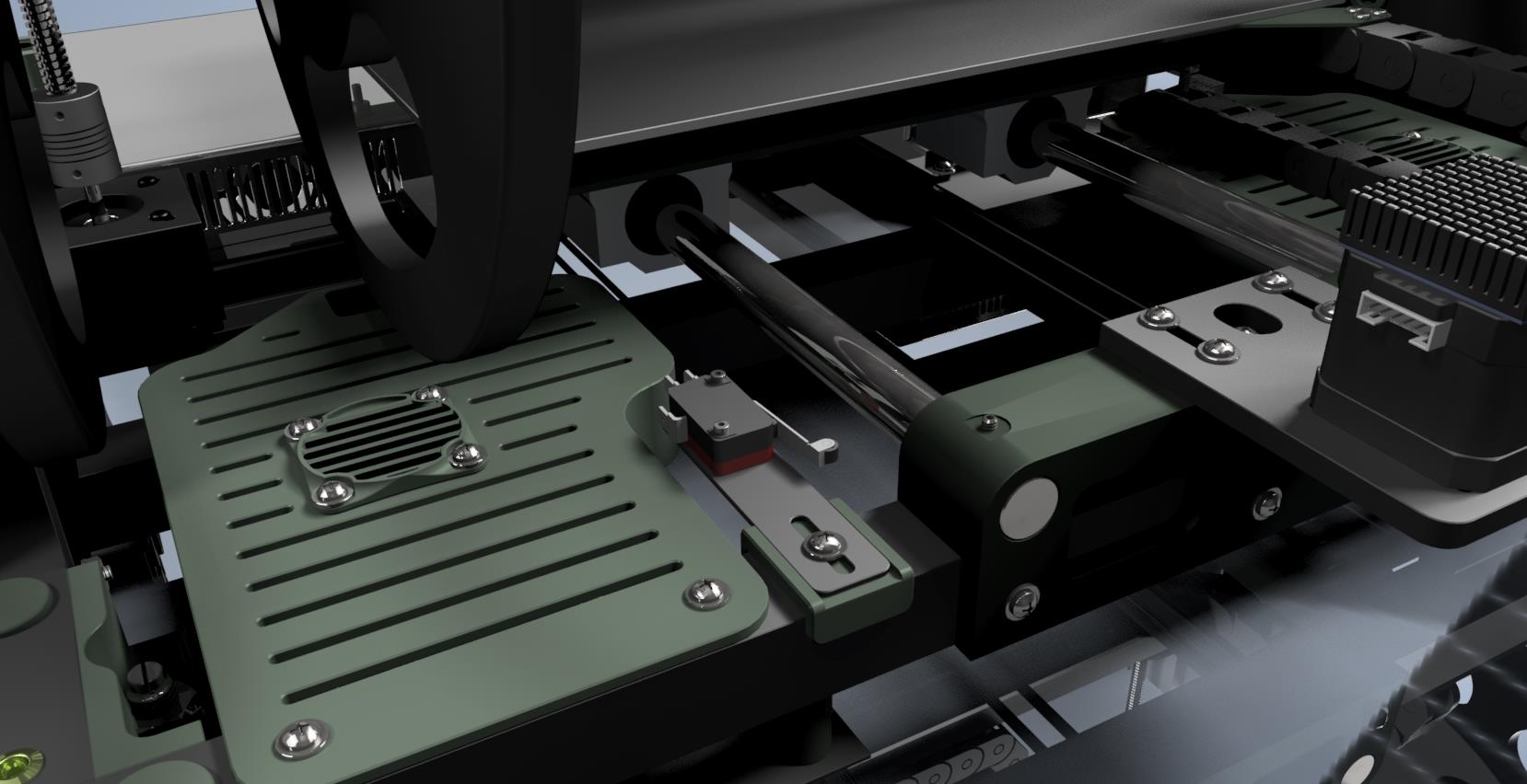
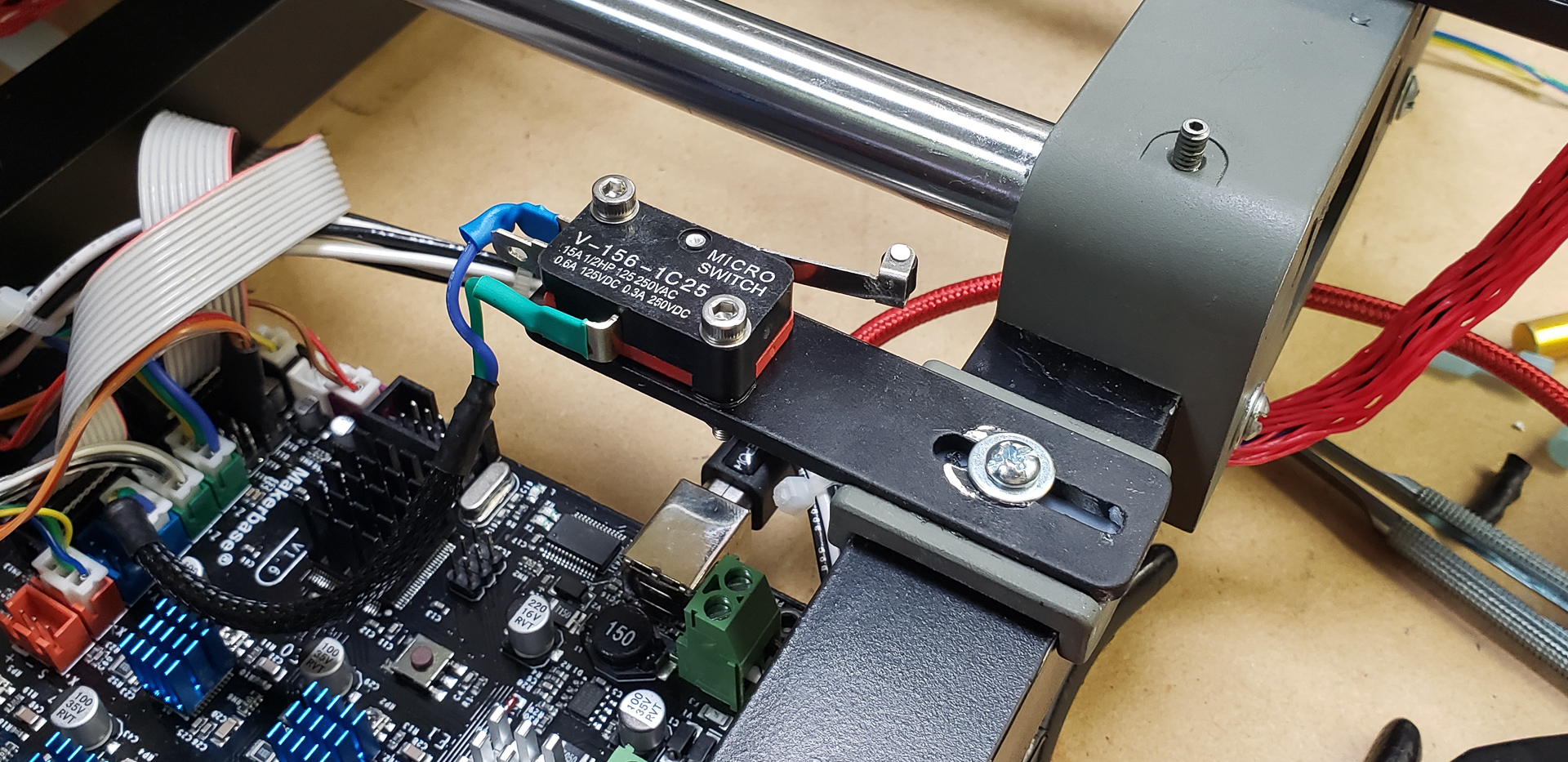
In normal circumstances, the endstop is adjusted once and left as-is permanently. For this reason, I didn’t bother with any complicated adjustment mechanisms.
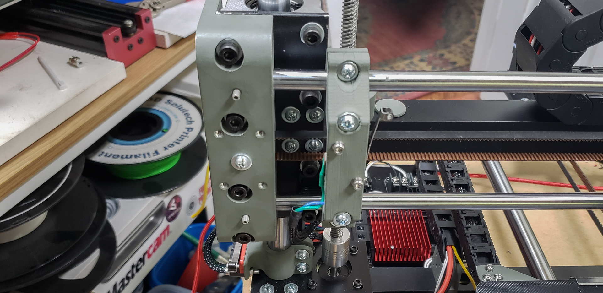
The X-axis endstop, however, turned out to be a bit of a mess. The initial mounting design I came up with ended up being completely useless. I don’t even have the model for it anymore, just a couple of photos:


What I was thinking when I made that “ear,” I’ll never know. Securing something like that to a polished, well-oiled steel rod is obviously not a great idea. It would rotate, sure, but worse — it had a tendency to slide backward whenever the carriage bumped into it. Inevitably, I tightened the screw too hard, and the mount simply cracked… which isn’t surprising given that it was made of photopolymer resin.
Fortunately, by that point, MARSH TURRET had already started attempting its very first prints. I temporarily taped the remains of the first mount in place and modeled a new one — more robust and reliable.
I’m not entirely sure anymore, but this might actually have been the very first functional part that Turret ever printed:
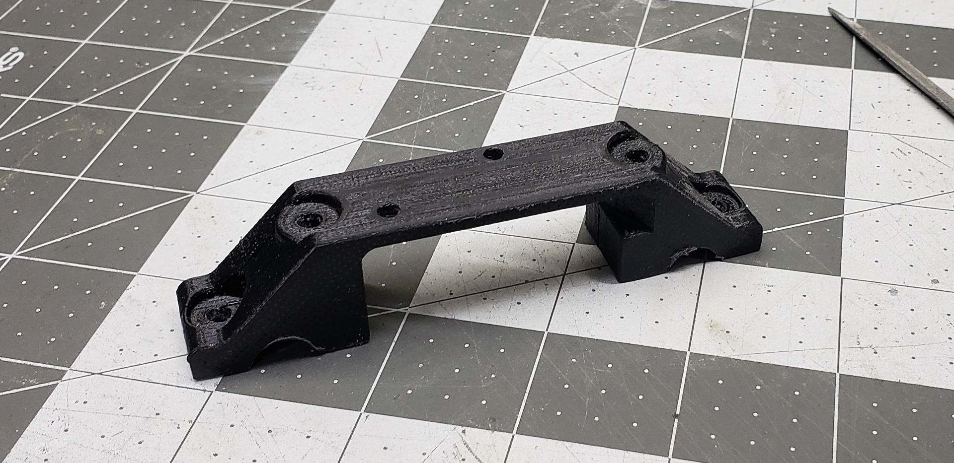

All the usual test prints like boats and other random stuff came after this mount. The print quality at that time was absolutely atrocious, but it worked nonetheless!
This mount solved all the problems. Unlike resin, the plastic is more flexible and doesn’t crack as easily — I can tighten the screws as much as I like. Now, the endstop stays firmly in place and doesn’t budge.
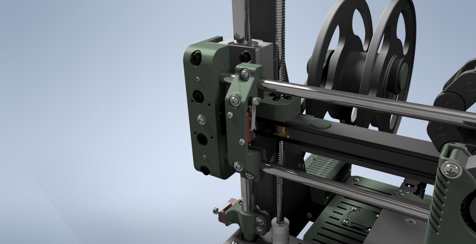
The Z-axis endstop was even more interesting. It also needed to be mounted on a rod, so I printed a mount for it using photopolymer resin:

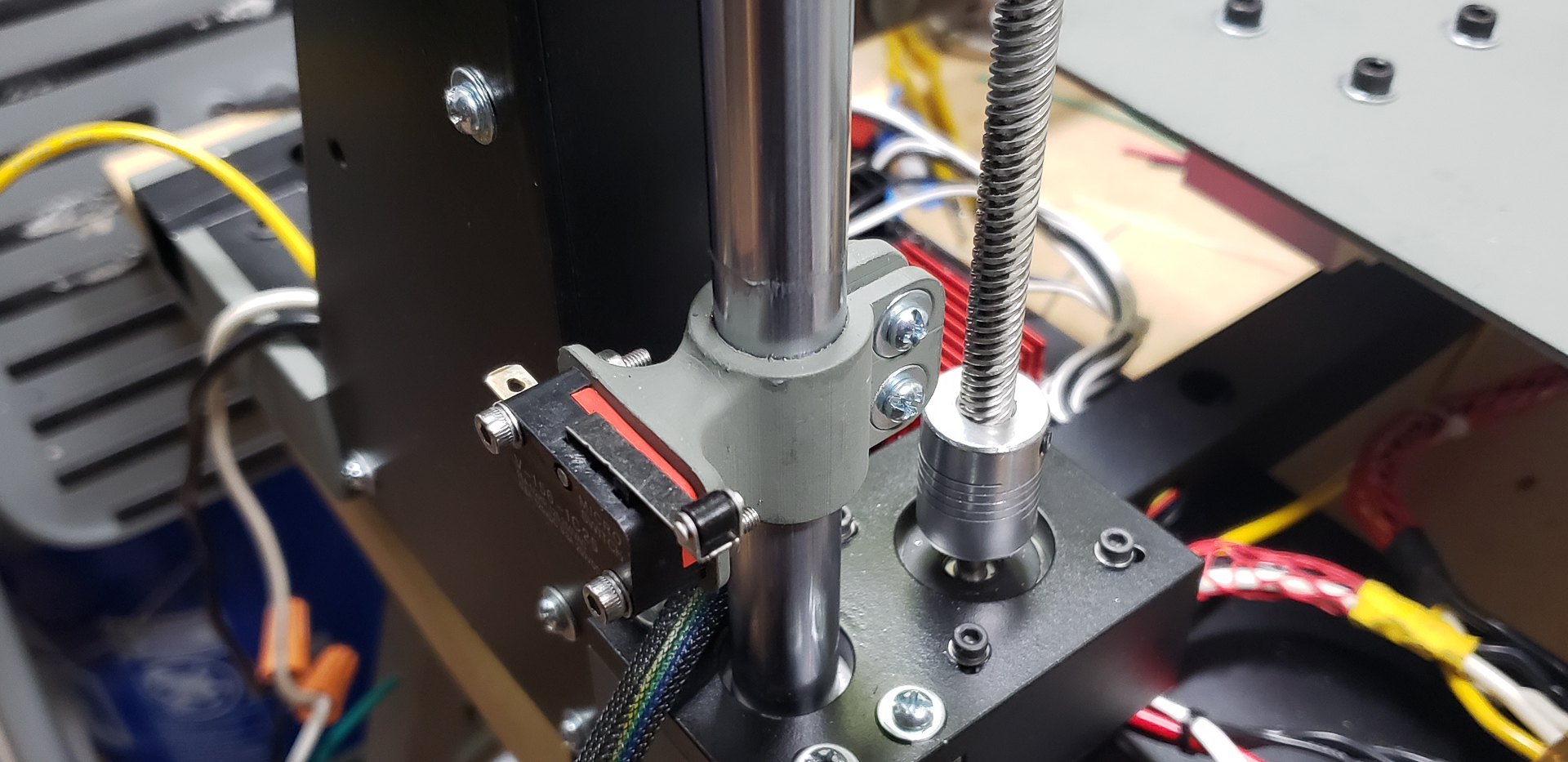
However, the rod for the Z-axis is much thicker, and the mount itself is bulkier. Overall, this version sits in place quite securely.
What’s interesting here is that this endstop isn’t even necessary! That’s because of BLTouch:
The Z-axis mechanical endstop was included in the design purely for system uniformity and serves only as a backup. In fact, it’s currently positioned below the contact zone, and the Z-axis carriage never even reaches it.
Of course, this is pure paranoia on my part. The voices in my head keep going, “Ooooh… BLTouch is just an electronic gadget… Who knows how long it’ll last… What if there’s a war and it breaks… blah-blah-blah, ke-ke-ke…“
So, it’s there, just hanging around, not asking for much. Serving as a backup… just in case.
Wiring. Lots of wiring. A LOT of wiring!
This time, I decided to pay special attention to the wiring — even more than to the electronic modules themselves. The spaghetti of cables sprawling in all directions drove me mad with Widow. This time, everything had to be tidy. Nothing sticking out, nothing dangling, nothing catching on anything. Everything had to be organized, accessible, and repairable.
For this project, I relied heavily on JST SM connectors. In my personal experience, they’re the most reliable and convenient for this purpose:

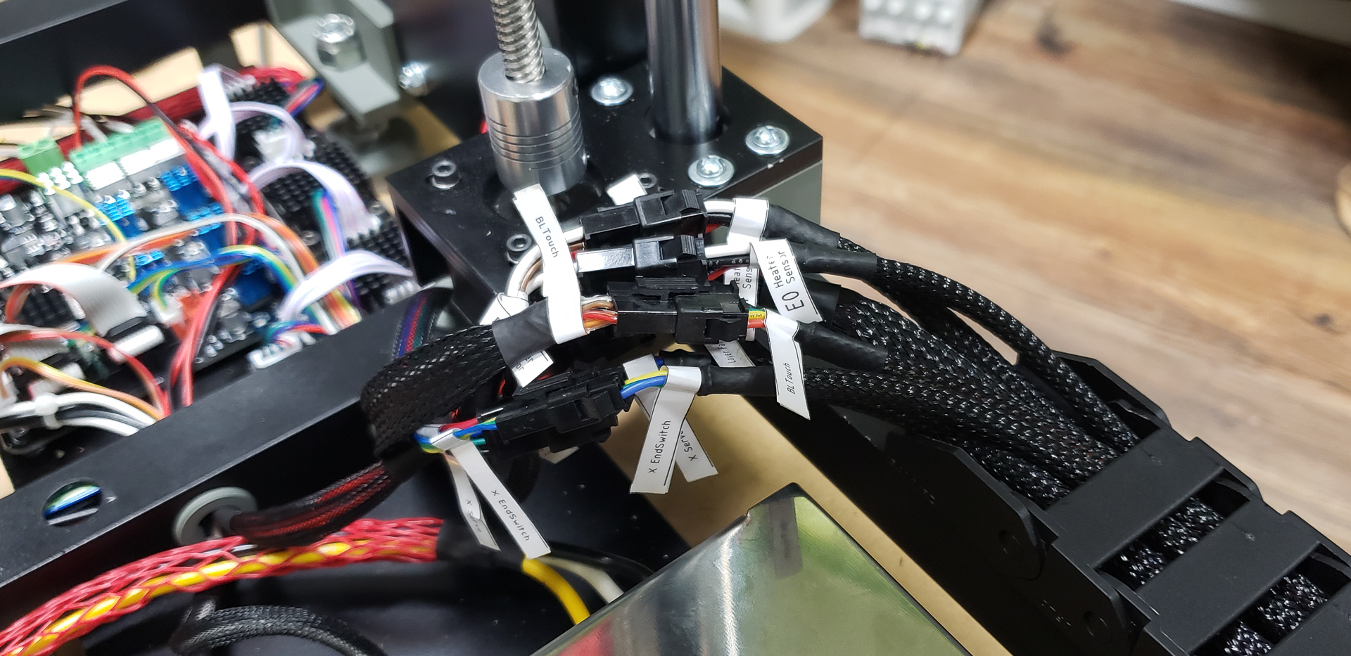
All the wires in the printer were meticulously grouped into independent branches. I still remember the time with Widow when I needed to replace just one wire on the print head. I ended up having to disassemble half the printer! That one long, continuous wire couldn’t just be pulled out of the tangled mess. Never again! Even if it meant wearing out my crimping tool to the handles, I vowed to never deal with something like that again.
Some wires were hidden directly inside the printer’s frame — the ones that, realistically, would never need replacement or repair. This mostly applied to wires connected to non-moving parts of the printer, such as the Y- and Z-axis endstops, which are mounted on the frame and remain stationary for years. Similarly, signal wires between MOSFETs and the controller fall into this category. Another example: the high-voltage wires running from the outlet through the power switch to the power supplies. These are thick, multi-strand 14-gauge wires that, given the printer’s loads and voltages, are practically indestructible. All of these wires were tucked away inside the frame, out of sight and out of mind.
It’s a different story with the mass of wires running from the controller to the moving parts of the printer. There are far more of these than the “stationary” ones.
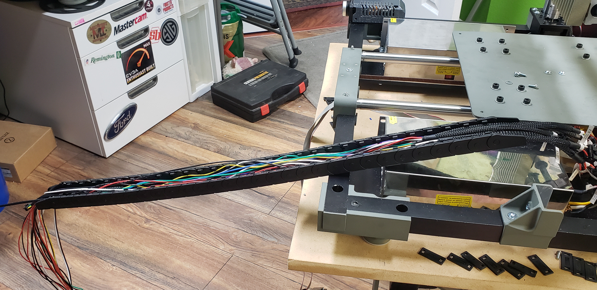
The only non-moving part of the printer is the frame itself. There’s hardly anything to connect to it, except for a couple of extruder motors and the ambient lighting (which I ultimately decided not to install). All other parts of the printer are in constant motion, and to route wires to these parts, you need flexible cable chains like these, which look like tiny tank treads:

Even these chains can’t fully protect the wires. I’ve already mentioned the periodic need to replace or repair wires. Even in these chains, where wires are seemingly secured and bend gently, they still occasionally break. This is especially true for the X-axis. In the photo above, you see the chain for the Z-axis. The Z-axis moves slowly and rarely, so I haven’t had any wires break there yet. But the X-axis darts back and forth like a squirrel being chased by a rottweiler, and the wires for that axis systematically fail from constant rapid bending and unbending.
Lately, I’ve been using flexible silicone-insulated wires in my projects. They’re far more durable in this regard than standard wires. In my previous printer, as I gradually replaced broken stock wires with these silicone ones, the number of issues decreased significantly. Not a single silicone wire has broken since. Unfortunately, I never fully transitioned Widow to the new wires, so things kept breaking here and there until the end.
With this printer, I exclusively used silicone wires from the start, in 18, 20, and 24 AWG, depending on the load. Even so, I designed the wiring with the concept of modular replacement in mind, allowing individual sections to be swapped without having to run new wires from the controller to the component every time.
Each branch has a connector before entering the chain and another upon exiting. If a branch transitions between chains, it gets another connector at each transition.
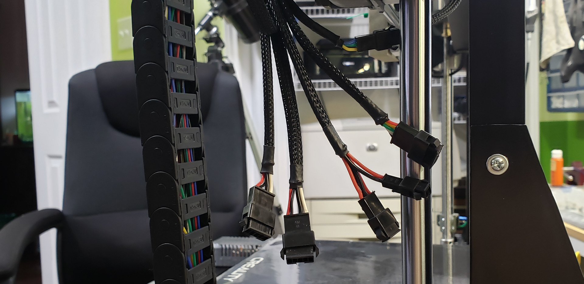

I’m aware of the general electrical engineering philosophy that “fewer connectors mean fewer problems.” Any connector adds complexity and reduces reliability in a circuit. But in this case, it’s justified. Wires aren’t cheap, and replacing a one-foot section is far preferable to replacing three or four feet of an entire branch. Not to mention it’s technically simpler. It’s much easier to troubleshoot a broken wire in small segments using connectors than to guess where it failed in a long, continuous stretch.
Moreover, it’s always possible to disconnect an entire chain, take it to a workbench, and work on it comfortably rather than fumbling inside the printer, standing on one leg with a soldering iron in your teeth.
Yes, organizing all this spaghetti took two boxes of JST connectors, and I dreamed about my crimping tool for several nights. But it was worth it!
Aside from the long, tedious process of routing wires, I also had to tackle the issue of securing the chains. For the frame, these mounts were 3D-printed from photopolymer resin:
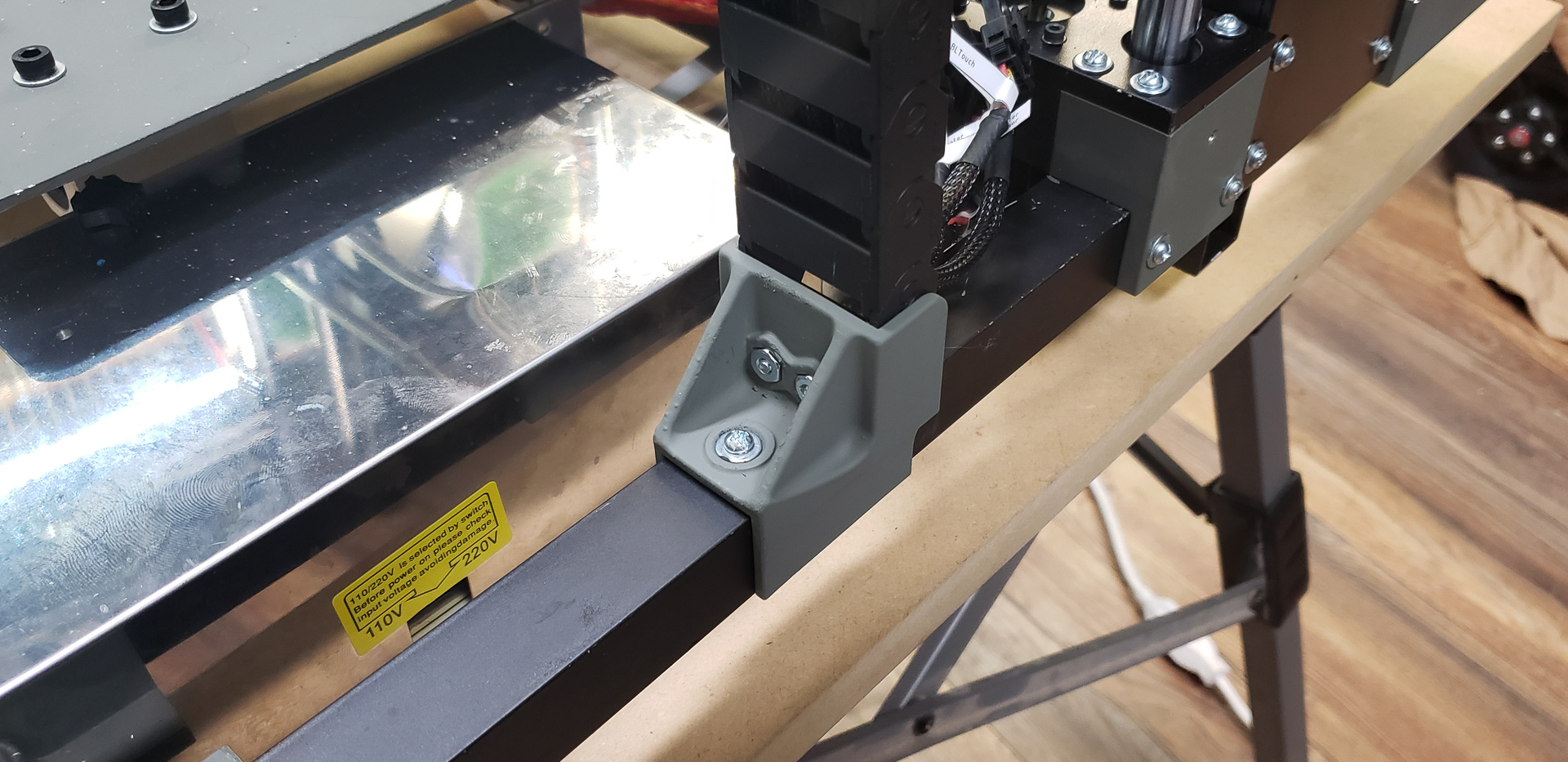
These are for the stationary ends of the chains, which don’t bear any significant load.
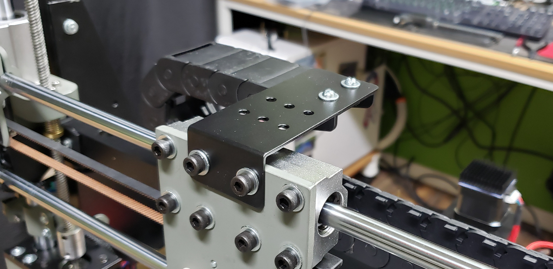
It was a different story for the mounts on the moving parts. Here, I had to put aside the epoxy and return to working with metal. This was especially true for the X-axis chain mounts:
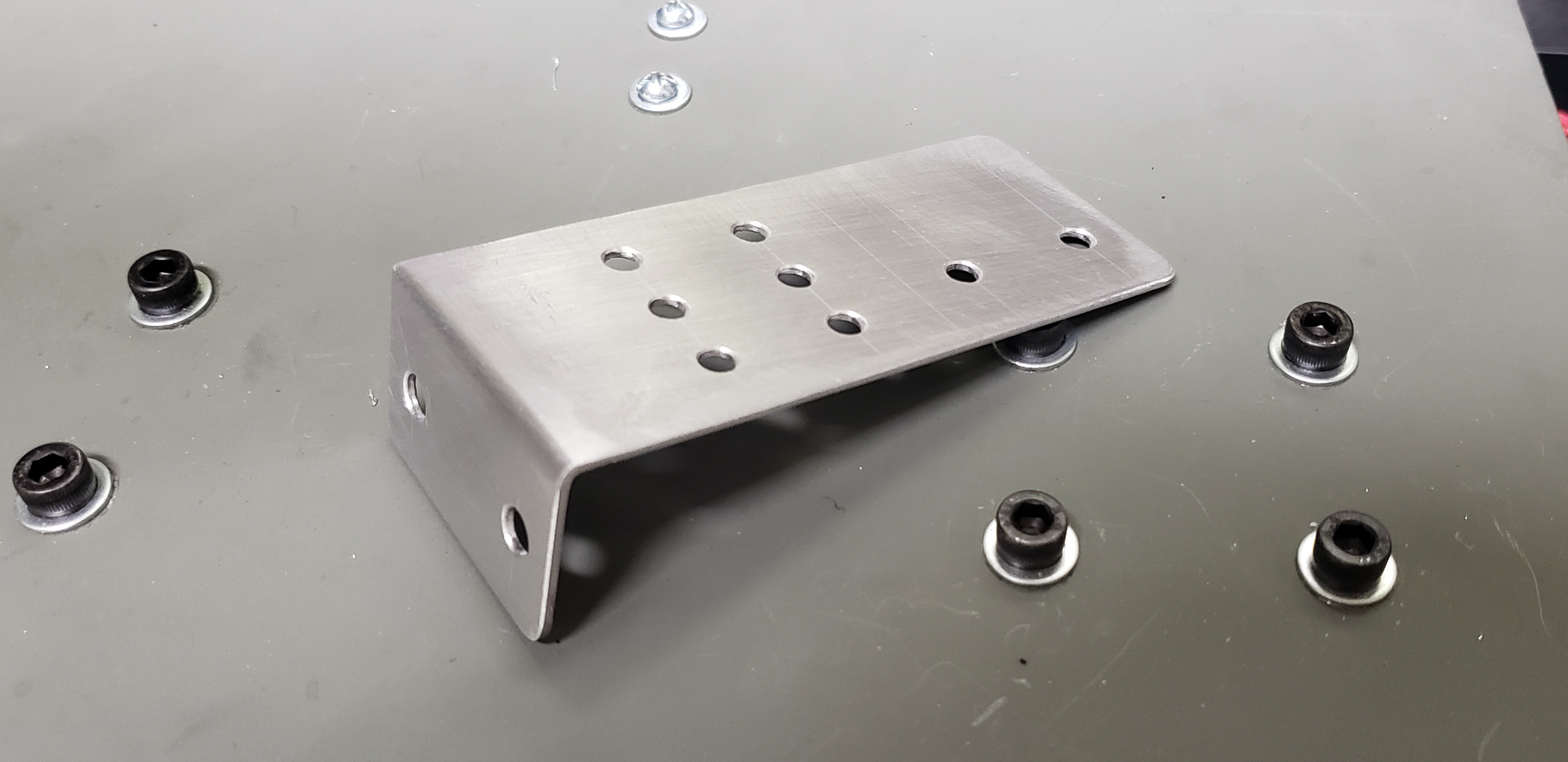
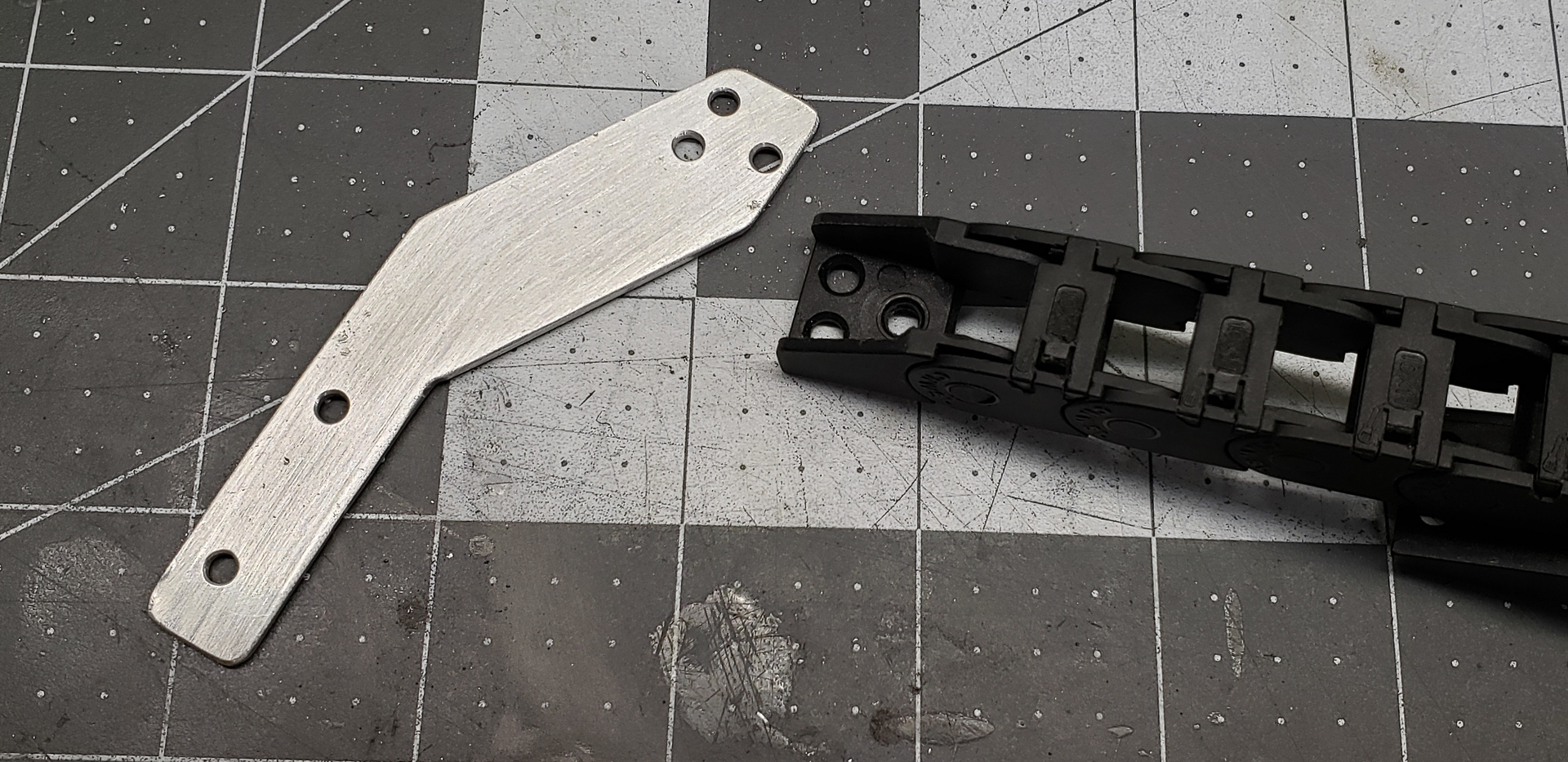
…and the “hot bed,” aka the Y-axis.
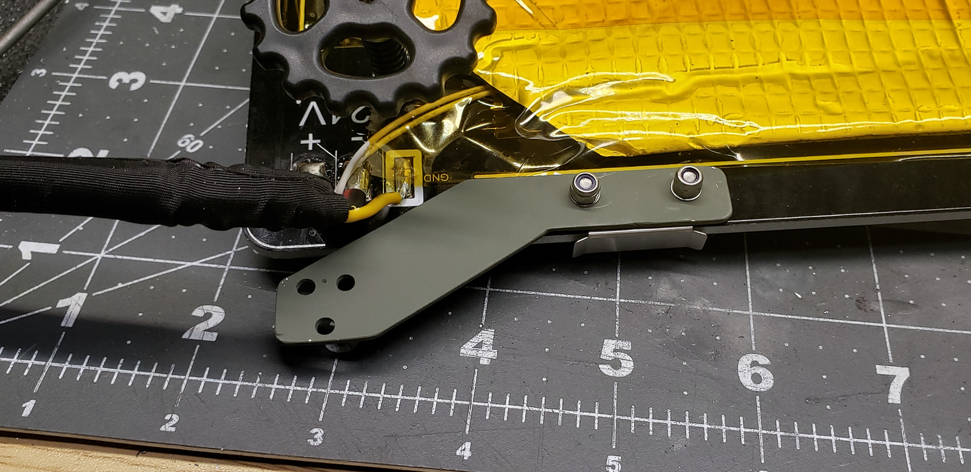
The latter required some creative problem-solving. The bed was pre-assembled, and I didn’t want to drill holes in it (there was a risk of damaging the heating element inside). So, I had to craft a custom-shaped mount that attached to the stock screws used to secure the glass clips to the bed:

Bit by bit, the printer’s spaghetti was tidied up to the point of being nearly invisible while remaining accessible for maintenance (and out of reach for nibbling):

Although wire-chewing is mainly the Cat’s vice — I’ve mentioned before that he once ate the wires in a mechanical dog’s head. He’ll have fewer opportunities to do that with the printer. Then again, cats are notoriously mischievous. I’m sure he’ll figure something out. However, the hours of flight practice he received as punishment last time should keep him deterred for at least six months. We’ll see…
And finally, the protective covers for the electronics.
There was no need for anything overly elaborate in this regard. Most of the main components are located within the printer’s frame and are largely protected by it. Elements like the power supplies don’t require any additional protection at all. They’re practically monolithic aluminum bricks as it is.
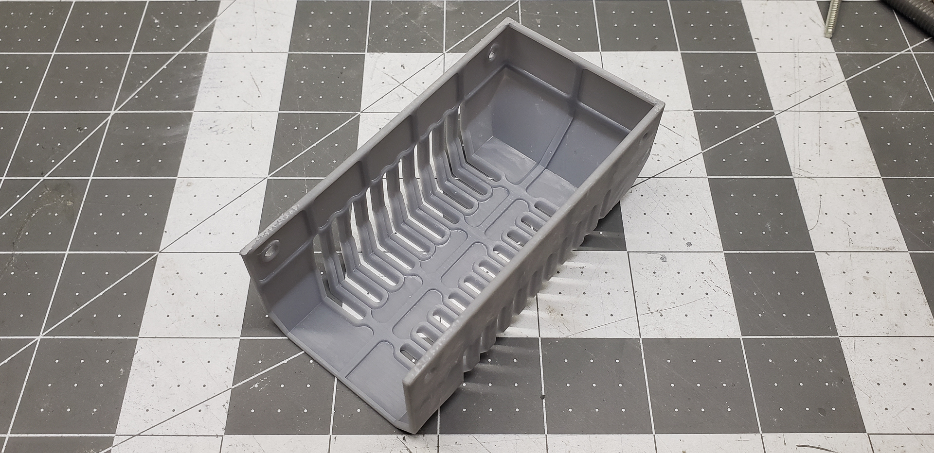
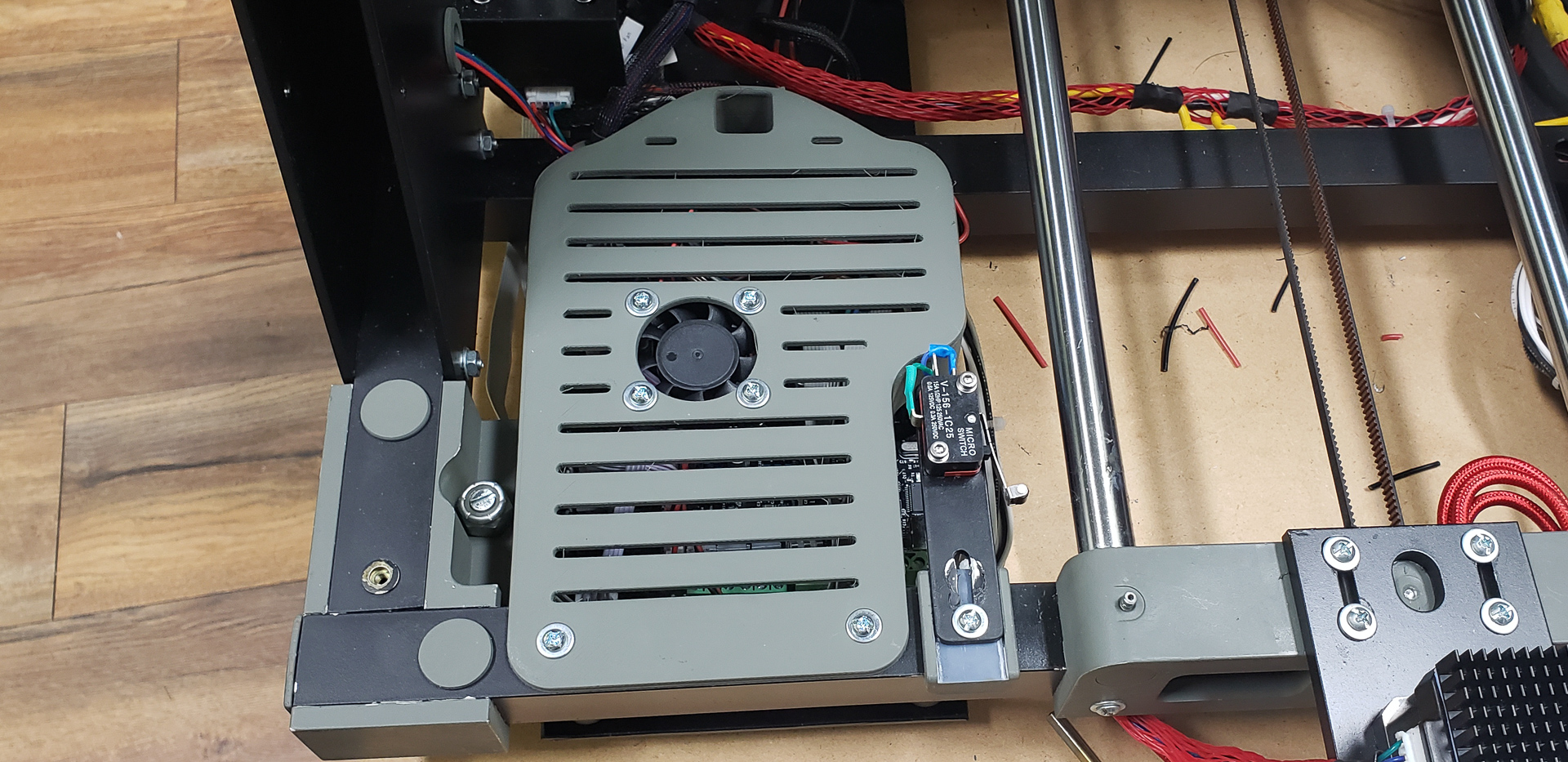
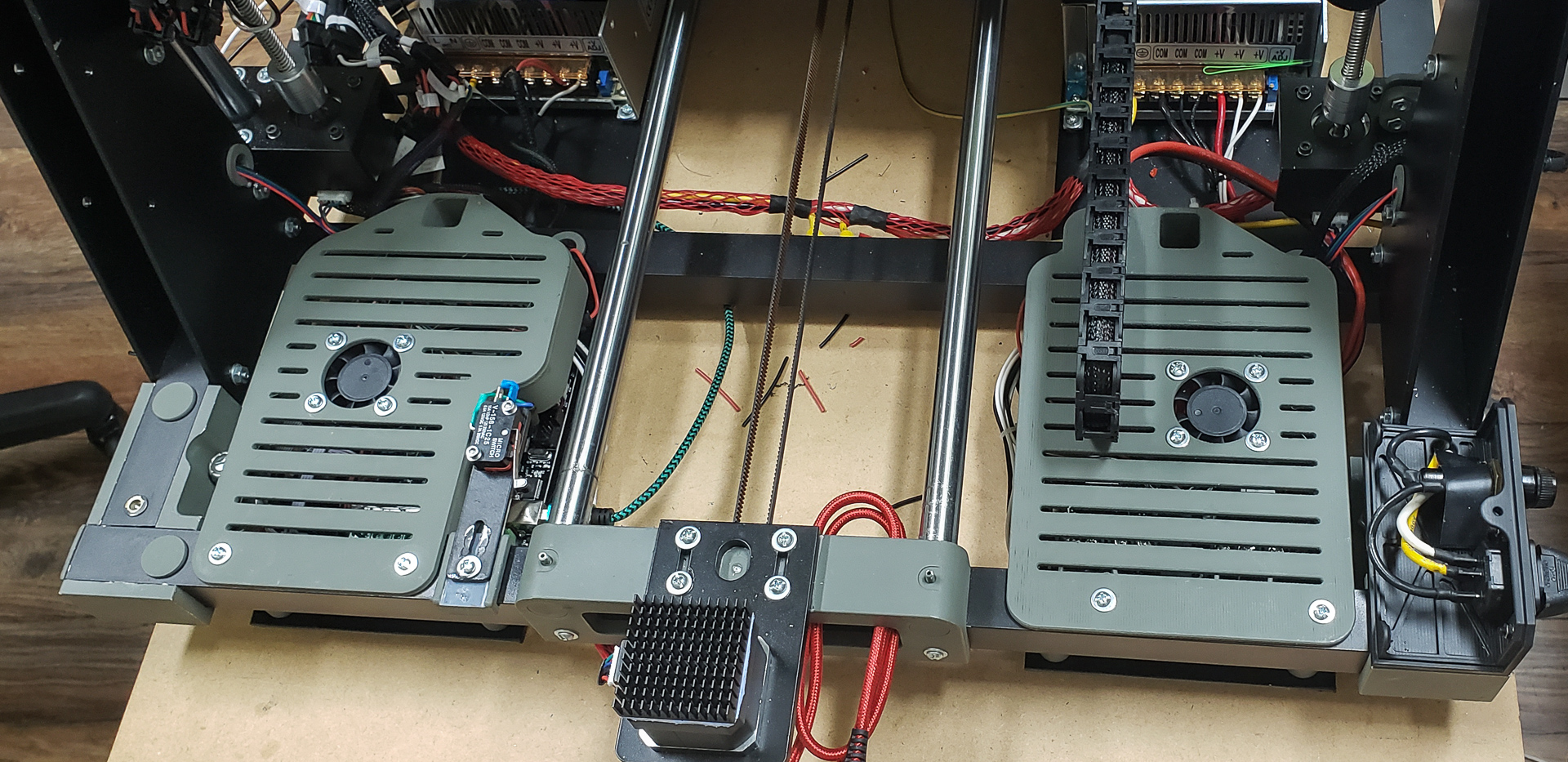
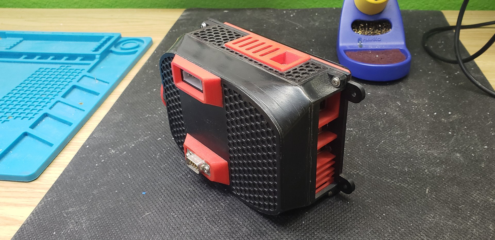
Only the components mounted at the rear of the printer required some sort of top cover. On top of that, they needed airflow to dissipate heat from the heatsinks, and a cover proved to be a convenient way to mount fans:

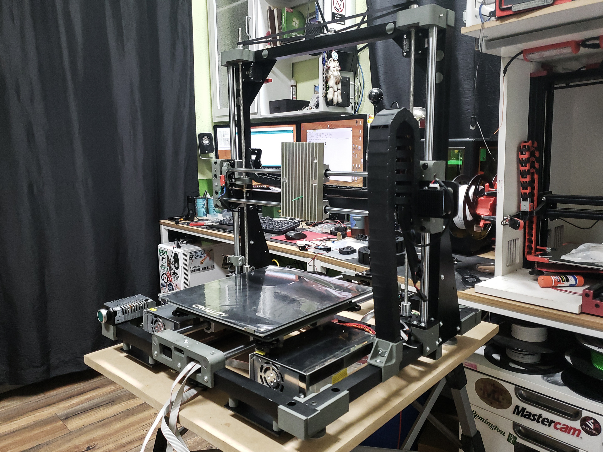
At this point, Turret started making parts for itself:

I used up the remnants of old plastic stock for this. It needed to be “written off” anyway since it had been sitting in storage for so long that it was starting to dry out. And since the covers were going to be painted, the color of the plastic didn’t matter at all. It was a good excuse to refresh my material supplies.
The protective grills for the heatsinks could have been printed by Turret at this stage, but they were actually made earlier, alongside the mounts for the endstops, using photopolymer resin — back when Turret wasn’t capable of producing anything like that yet. At the time, I just set them aside for later. When “later” arrived, all that was left was to paint them and install them in place:
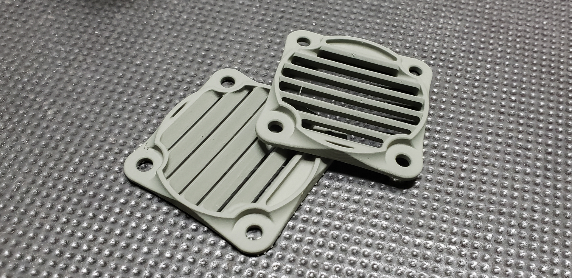
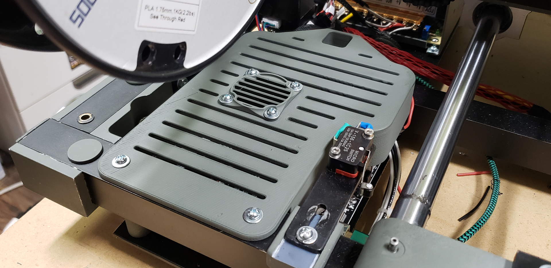
Installing these grills on the covers for the electronics blocks became, in effect, the final touch of the project.
In principle, a printer only needs its mechanical components, a single controller, and a power supply to function. All the MOSFETs, BLTouch, colorful screens, and other features are essentially upgrades that enhance the printer’s capabilities or make its operation more reliable. It’s great to have them, but they’re not critical.
The same can be said for connecting a Raspberry Pi with OctoPrint and a camera to the printer. You can absolutely get by without it — I’d estimate that around 80% of 3D printer owners manage just fine without this setup. However, for me personally, the additional functionality that a microcomputer brings to the system turned out to be so convenient and irreplaceable that it became a “must-have” feature.
During the printer’s design phase, equipping it with a Raspberry Pi running OctoPrint was considered from two fundamentally different perspectives.
- In one scenario, the microcomputer could act as the “central hub,” making the rest of the printer’s electronics — including the main controller — peripheral to it. The printer wouldn’t be able to function without this system, as OctoPrint would handle all interface functions, and the printer’s original screen and rotary knob would be eliminated.
- In the other scenario, the microcomputer wouldn’t serve as the central hub but would instead become a peripheral component itself, offering additional functionality.
The first scenario — where Raspberry Pi + OctoPrint take center stage — was how Black Widow operated. Although Widow retained its original screen as a vestige of its factory configuration, it was practically useless. The SD card slot for loading print files, for instance, wasn’t even accessible from outside the printer’s casing. The information displayed on the screen wasn’t reliable, as TEVO’s stock firmware had disabled controller feedback. The controller could only blindly execute commands received through the port, without attempting to interpret or visualize them on its display. All control and monitoring were handled exclusively through the Raspberry Pi and its interface.
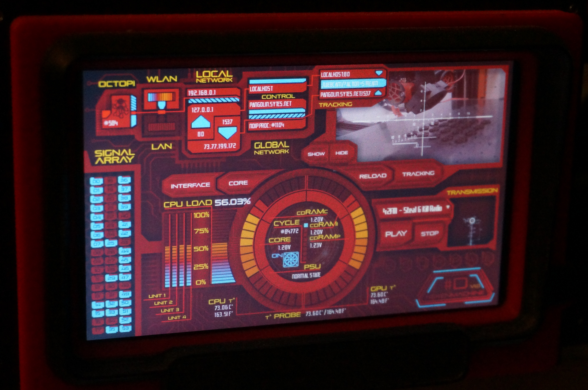
The Raspberry Pi itself, equipped with a large touchscreen, built-in SSD, and other goodies, looked like a full-fledged computer:
It could not only control the printer and stream video from its camera to the internet but was also packed with utterly over-the-top features like built-in online radio with a stereo system (because why not listen to music while printing?), a torrent downloader (hey, it’s going to be printing for days, might as well download something in the meantime), and even a media player for watching movies. It also had an HTTP server, of course… Yeah, it was a lot.
You might laugh, but at one point, I even added a microphone and taught the Raspberry Pi to respond to voice commands like “Preheat for PLA/ABS” or “Start/Stop/Pause.” But this feature was eventually disabled because the Pi struggled to handle everything at the CPU level. It would either ignore commands, lag video, or even pause printing for a few seconds while it internally “thought” about something.
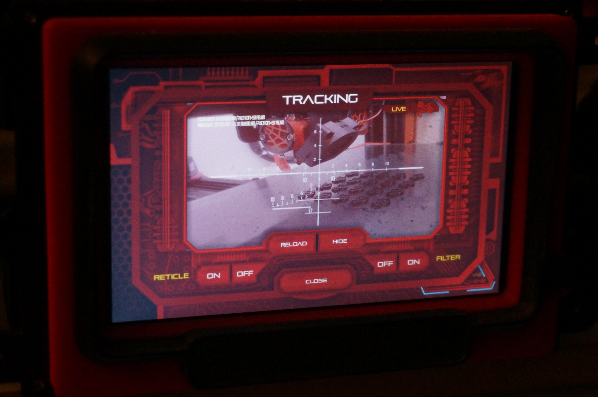
The custom interface I developed for this monstrosity could awe and terrify any unprepared guest who happened to stumble upon it:
Let’s face it — with such a powerful onboard computer, not only did print control cease to be the printer’s primary function, but the entire printer itself turned into little more than a decorative stand for the Raspberry Pi.
I can’t clearly explain how it escalated to this point… Initially, I just wanted the printer to display the camera feed onboard as well as externally. But then, as they say, “that madness could no longer be stopped.“
With MARSH TURRET, after careful consideration, I decided not to follow the same path as with Black Widow. This time, the Raspberry Pi would serve as a purely utilitarian tool dedicated solely to the printer. It would act as a network interface with enhanced capabilities, as originally intended by the developers of OctoPrint. No displays or touchscreens with “wow!” interfaces, no SSDs, and no additional programs or scripts unrelated to the printer’s operation. Just a bare-bones Raspberry Pi, OctoPrint, and a camera.
However, one useful idea from past experience was carried over: a Z-axis-mounted camera holder that allows the camera to rise along with the printed part as it “grows” on the bed. This way, the current printing layer remains in view up close, avoiding the situation where the camera’s focus drifts out of frame and becomes useless for monitoring. This solution proved surprisingly effective in the past and made sense to include in Turret’s setup.
So, here it is: the Raspberry Pi and camera in their minimal configuration:

The decision to mount the Raspberry Pi on the Z-axis was driven by the choice of a proper Raspberry Pi camera with a wide-angle lens instead of a modified PC webcam this time around:
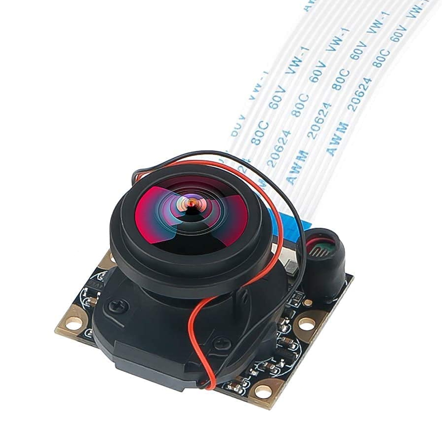
While the camera has many advantages, it also has a drawback: a wide, fragile ribbon cable that I absolutely didn’t want to run through two flexible cable chains to a section of the frame where the Raspberry Pi could be mounted stationary:
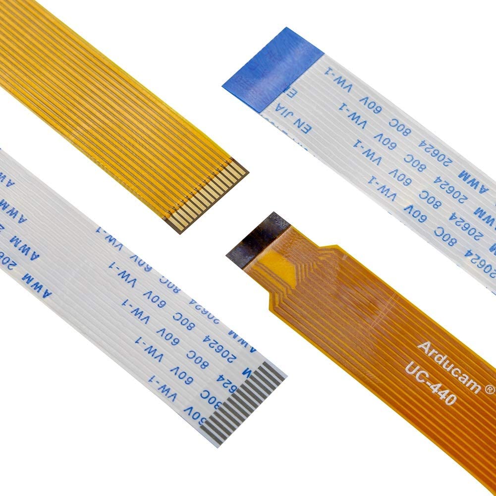
That ribbon cable wouldn’t last long under constant bending and unbending. Unfortunately, I couldn’t find a version of the ribbon in the form of a simple multi-core cable of sufficient length. I’m not even sure if such a thing exists. Making such a cable myself seemed overly tedious. Moreover, there was no reason not to place the Raspberry Pi in close proximity to the camera, and doing so solved… well, everything.
Of course, the Raspberry Pi’s power cable and the USB cable connecting it to the printer controller still had to be routed through the flexible cable chains along all the axes to the power supply section in the frame. However, these aren’t fragile ribbon cables as thin as a hair. They’re regular cables, durable enough to withstand repeated bending and unbending during the printer’s operation, making this setup entirely practical.
To simplify things even further, I decided not to bother with making a custom case for the Raspberry Pi. Instead, I used a heatsink case that serves the same purpose:

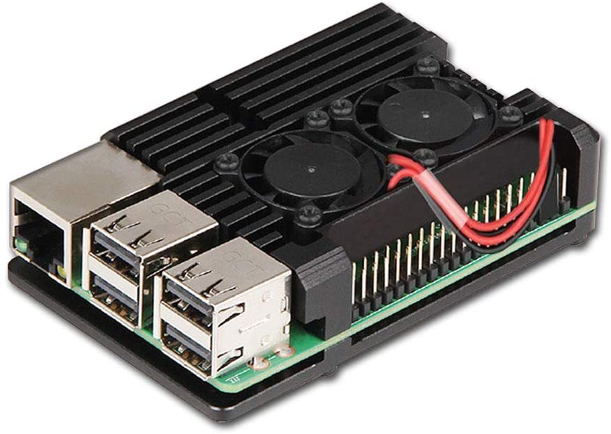

This heatsink case, made entirely of aluminum, covers all the Pi’s internals and even has built-in fans. This means there’s literally nothing else to do! Just screw in four bolts, connect the power, and you’re good to go. Simple, reliable, and cool.
Incidentally, I opted for the third-generation Raspberry Pi. The same version was used in Widow to handle its chaotic zoo of features, and it performed admirably — as long as I didn’t go overboard during my bouts of “creativity.” For running OctoPrint alone, the Pi 3 is more than sufficient. So, I decided against purchasing the newer “Pi 4,” and the few dozen dollars saved from the project budget were redirected toward buying a quality camera arm.
As the “arm” for the camera, I chose a flexible modular channel from Loc-Line:

Originally, these channels are used for directing fluids or air to the working area of tools (most commonly in various machines, engravers, etc.). However, DIY enthusiasts have long repurposed these modular channels for all sorts of creative projects — from desk lamps and “third hands” for soldering to photo stands and robotic manipulators.
At first, everything in this project was going so smoothly that Fate decided to throw me a curveball. In the plan, I envisioned the camera arm being made of black segments. This was the color included in the model:
In reality, however, black modules were only available in 1/2-inch or smaller sizes. With those, the arm would have been too thin and likely unable to reliably hold the camera. The project specified an arm built from 3/4-inch modules. I searched everywhere! On Amazon, I found some black-colored options, but they were all Chinese knock-offs of the original Loc-Line, with mixed reviews and absurd prices.
As the deadline loomed, I begrudgingly had to buy a set of segments in the “standard” obnoxious blue-and-orange color shown in the photo above. It didn’t fit the printer’s color scheme at all, but it was a reliable, original Loc-Line. I decided to take a philosophical approach and resigned myself to the color mismatch, hoping I’d figure out a solution for this aesthetic issue later. I had a couple of ideas…
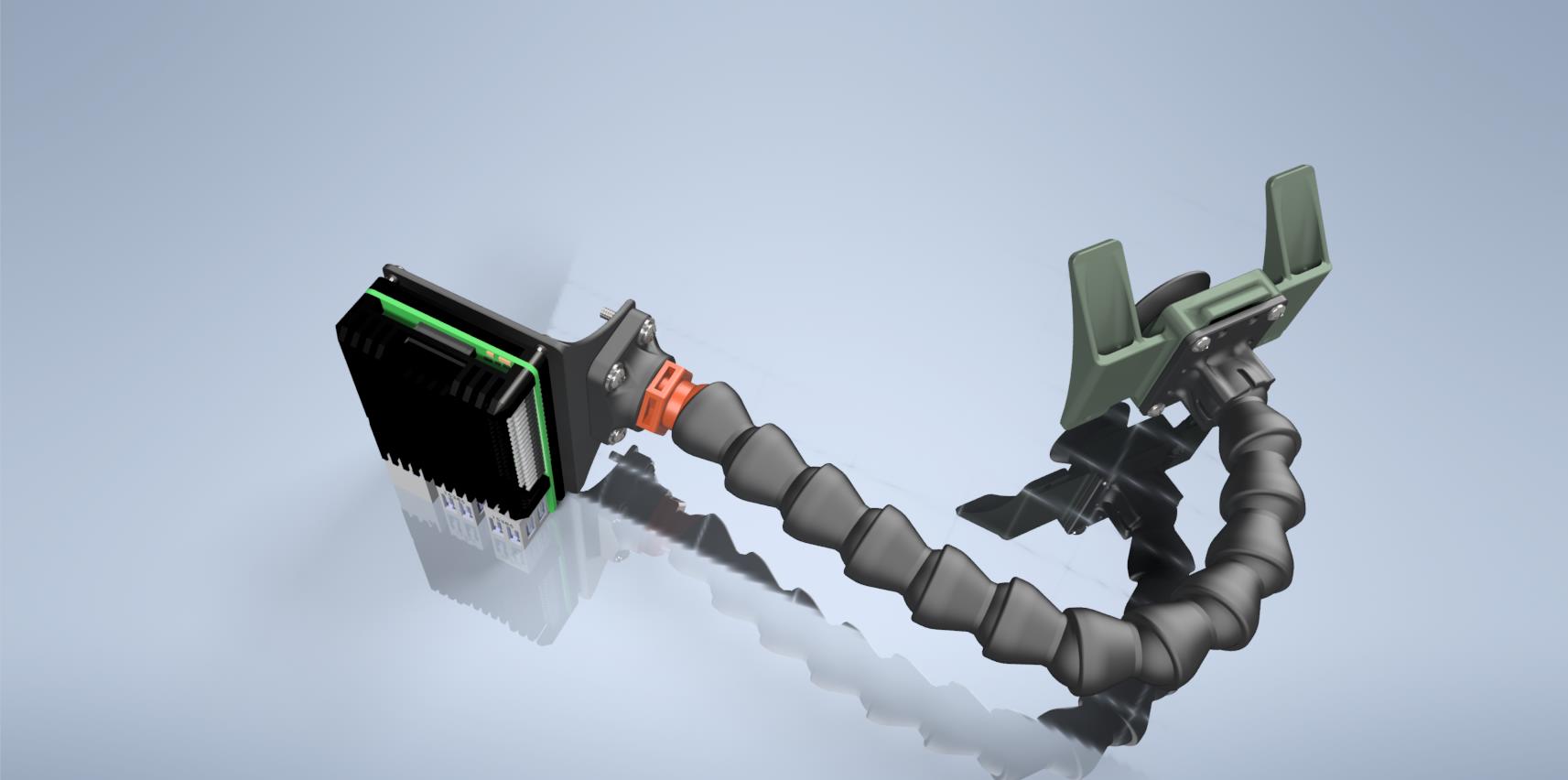
The camera housing was designed to use the same standard joint as the rest of the “arm” segments, making it just another module in the chain while retaining full freedom of motion for bending and rotation:
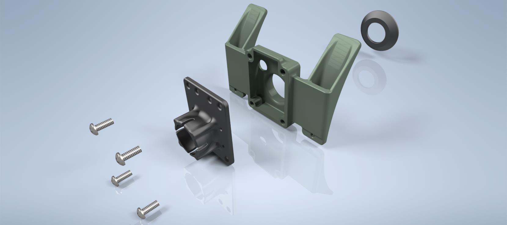
The funny “ears” on the sides of the front cover are meant for attaching LED strips to illuminate the camera’s field of view.
The entire mounting system for the Raspberry Pi and the camera was printed by Turret itself. By that point, Turret was more than capable of providing everything it needed:
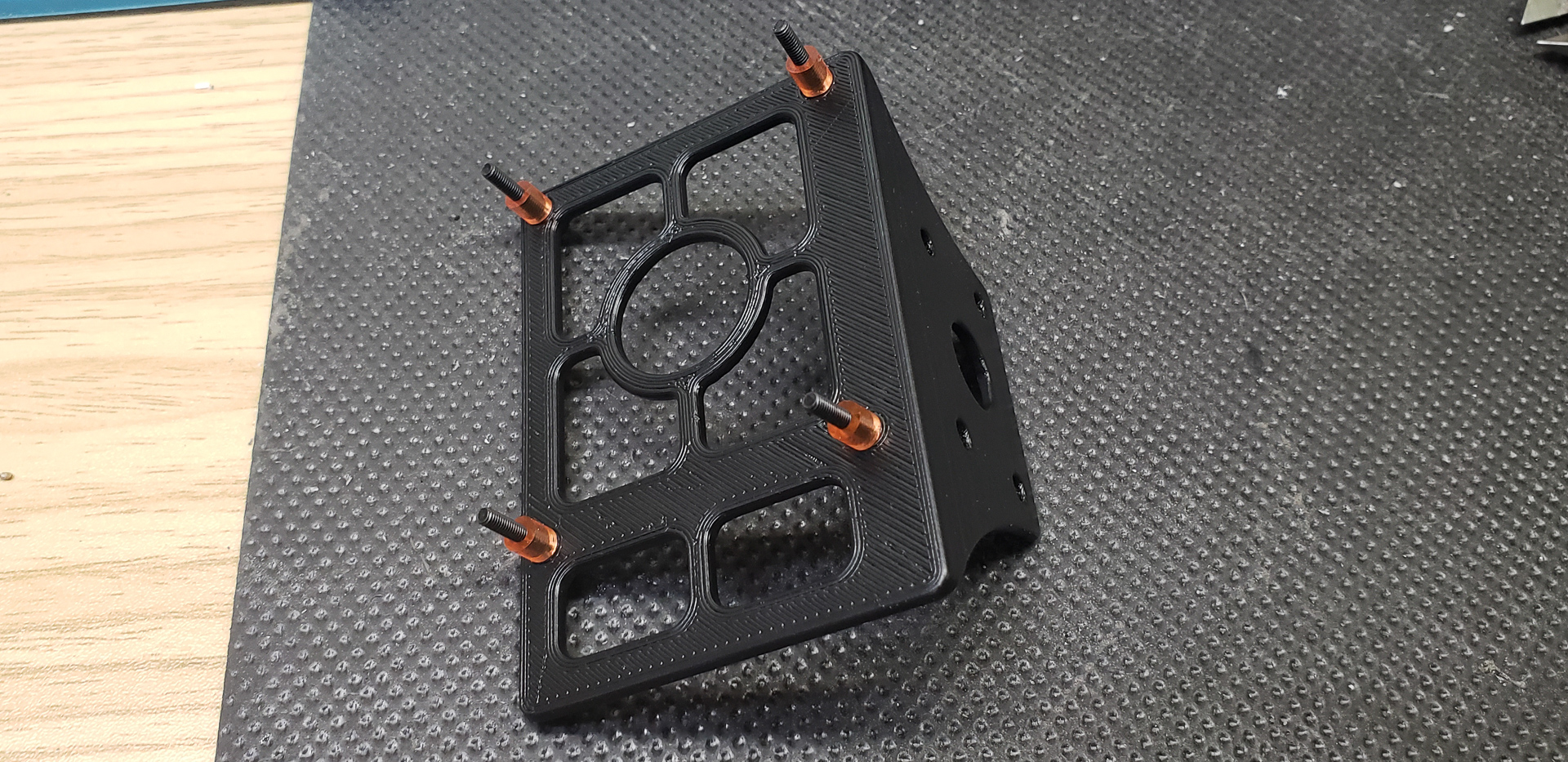
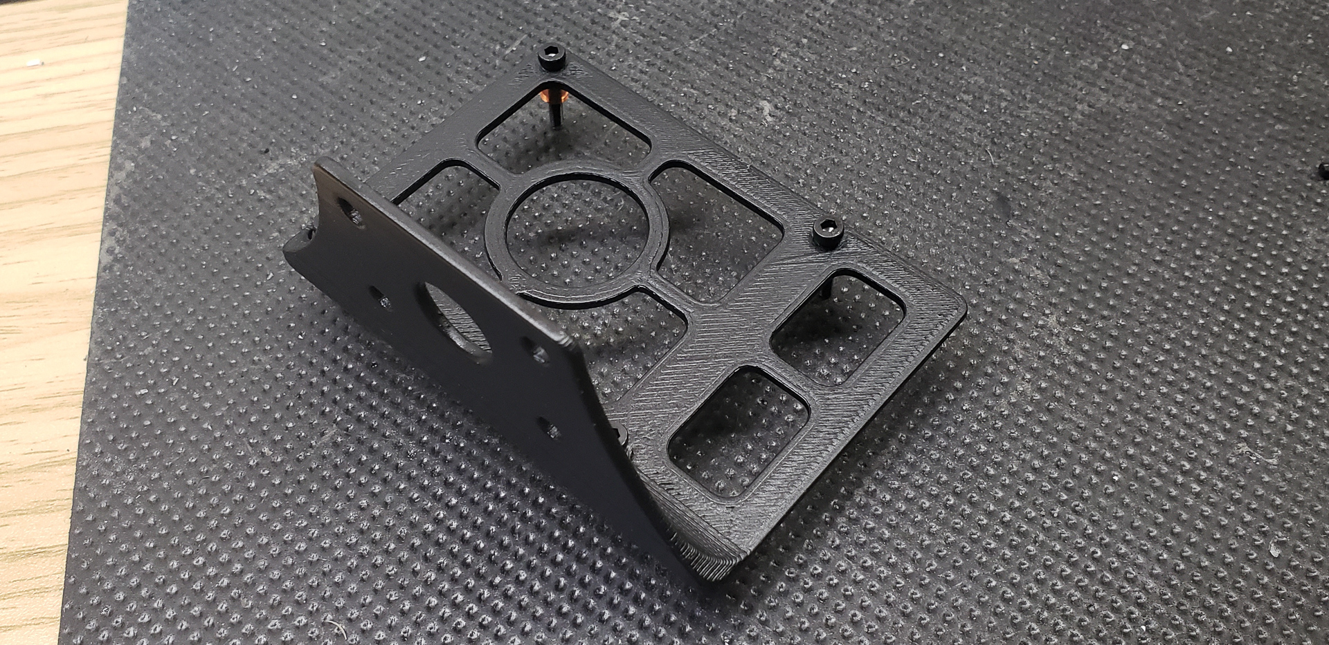


This mount serves as a single attachment point for both the Raspberry Pi and the camera. Easy to remove, easy to reattach.
Oh! I found a “behind the scenes” photo:
The Raspberry Pi on the printer was already operational, with OctoPrint controlling the print and streaming video online. While Turret was printing a proper camera mount, a “temporary substitute mount with a flavor identical to the real thing” was being used:
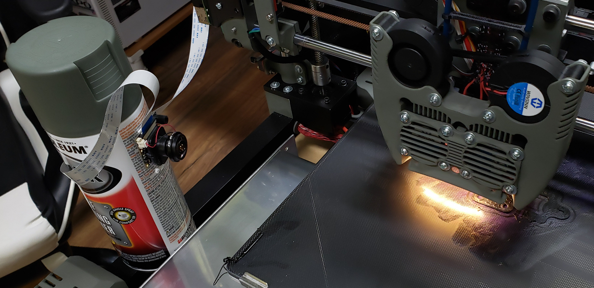
As Adam Savage says, “Every tool is a hammer.” You use whatever you have on hand.
The front section of the camera housing was printed using photopolymer resin since its shape was more critical than its strength:

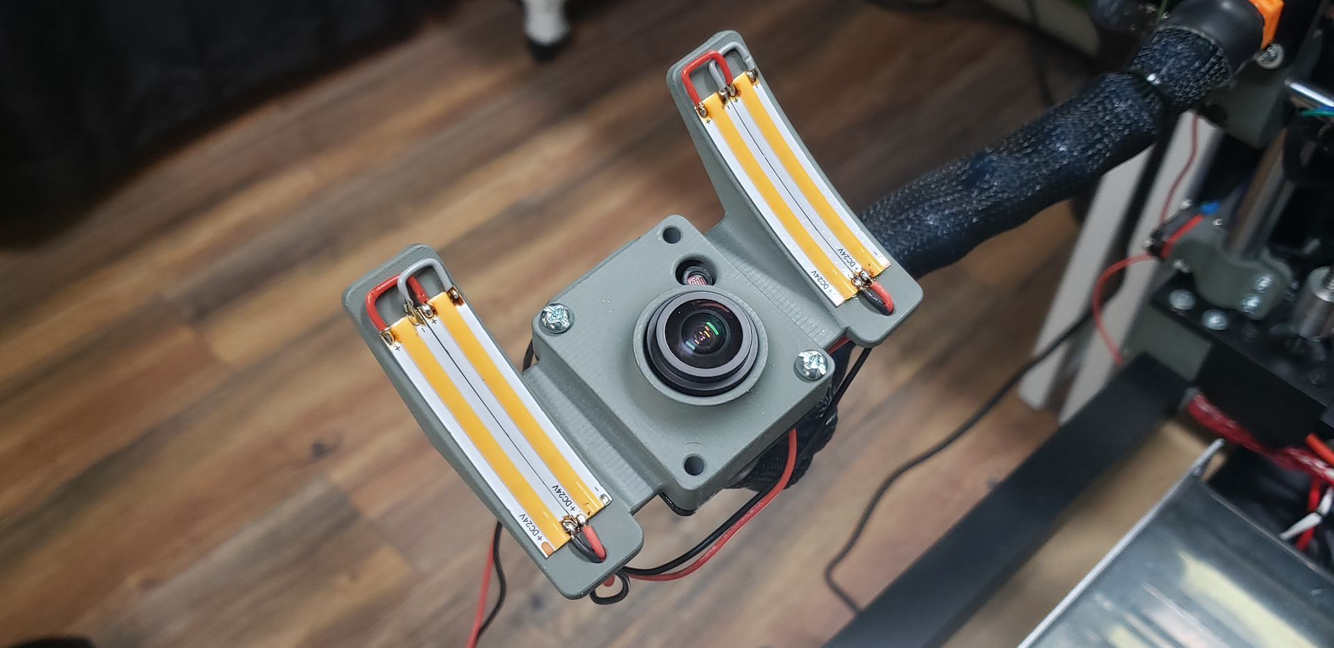
For lighting, I used four pieces of the same “dot-less” LED strip that I had already used in the printhead assembly.
And that’s it! Despite my near-uncontrollable urge to add lights and my insatiable desire to turn every device into a Christmas tree, this is all the lighting this printer has. Just one strip of LEDs under the printhead nozzle and four strips on the camera’s sides. And that’s more than enough!
Forcing myself not to wrap LED strips around the entire printer frame was the hardest part of the project. But I managed!
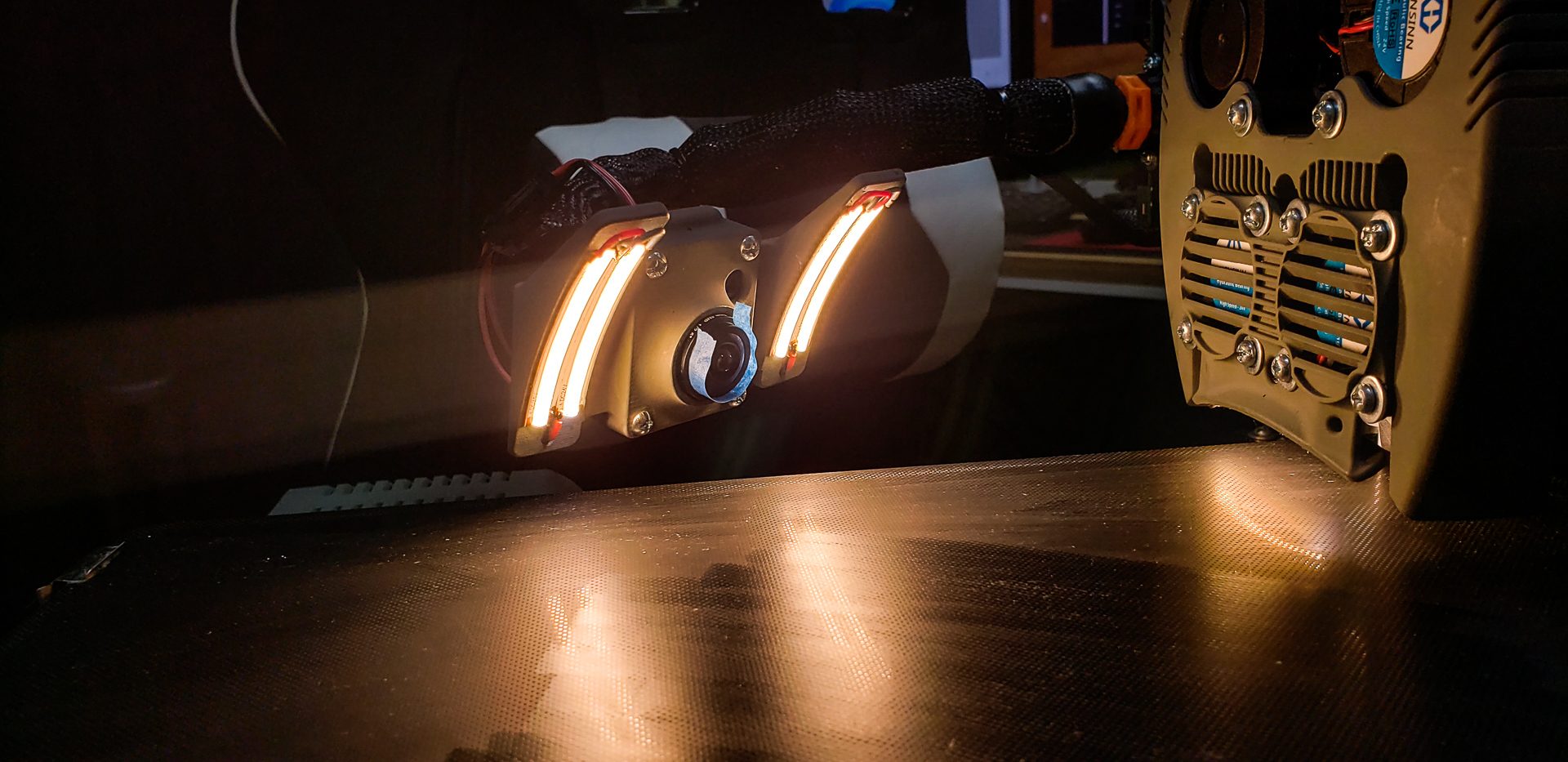
Unfortunately, I made a bit of a mistake with the “ears” on the camera housing. The LED strips mounted on them create severe side glare, which floods the wide-angle (170° FOV — practically fish-eye) camera lens. I didn’t account for this during the design phase and didn’t think about it until I saw the first video after assembly.
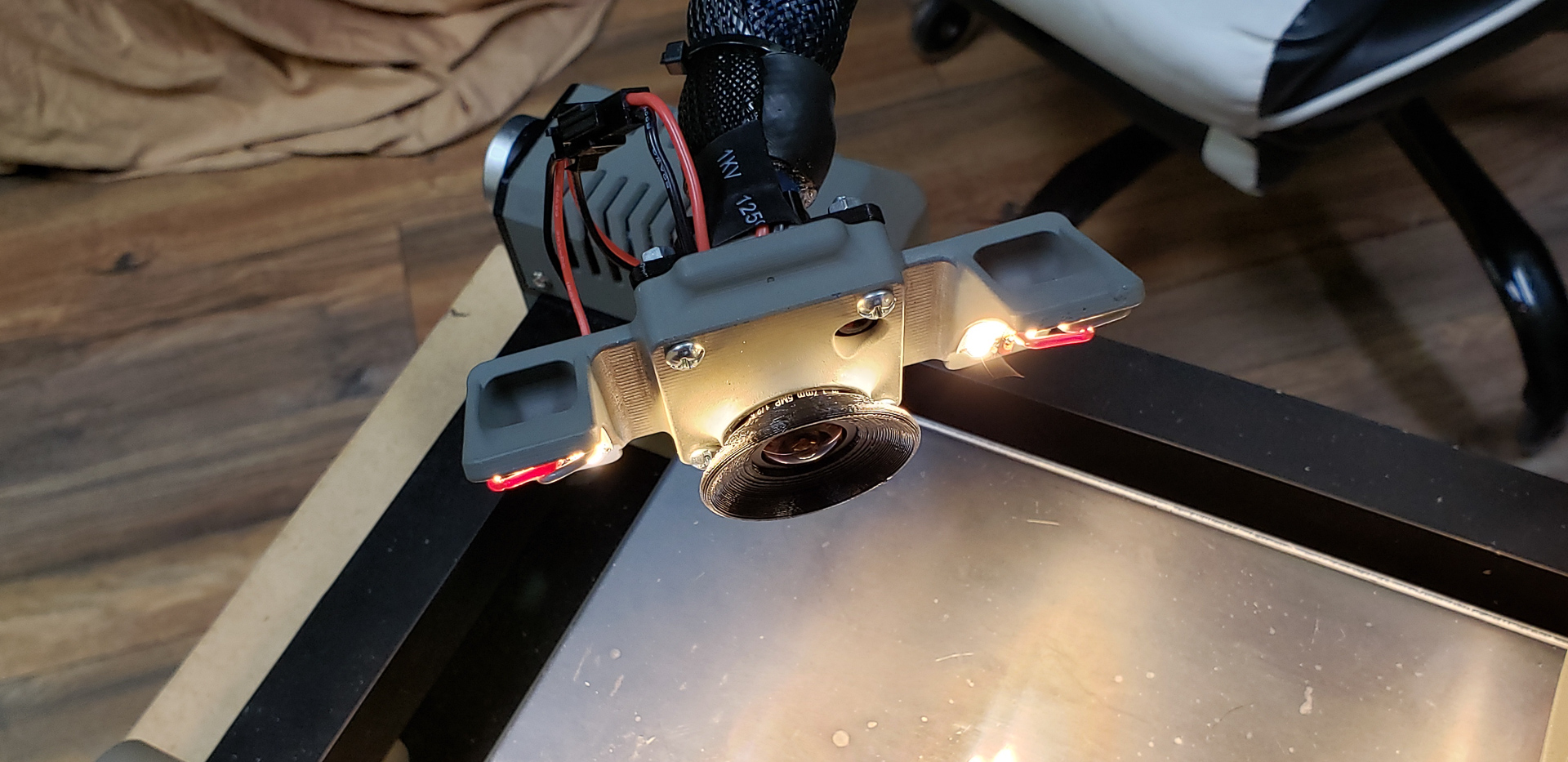
This issue was fully resolved by adding a lens hood to the camera. If you look closely at the photo above, you’ll see a strip of masking tape around the lens. That was me testing the hood’s height to ensure it wouldn’t appear in the frame while still blocking the side glare. The final hood looked like this:
At that point, one more issue remained, which I mentioned earlier — glare caused by printing with white filament.
In a brightly lit room, it’s somewhat manageable. But when I’m not in the room (i.e., when remote monitoring is actually needed), the lights are turned off. During the day, the room is almost as dark as night because its windows face the “sunny side,” and if I don’t close the blackout curtains completely, the temperature inside quickly becomes incompatible with human life.
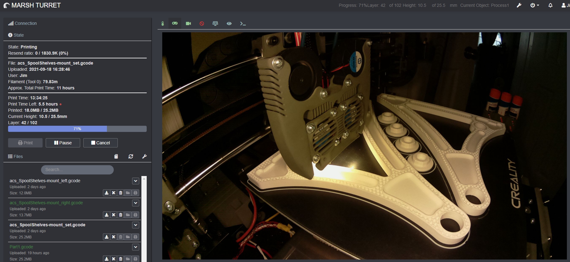
In a dark room, the printer’s camera produces this:
The printed object becomes overexposed, making it impossible to discern any details. This essentially makes remote visual monitoring of the print process useless.
This issue wasn’t caused by the camera or its housing but by system-level software settings. For some reason, the camera doesn’t enable automatic exposure mode by default. The image is adjusted based on the initial lighting conditions detected when the printer starts — typically an empty matte black bed. The camera doesn’t adapt when a bright object starts “growing” on the bed, resulting in overexposure since the printed object is usually much lighter than the black bed the camera was originally calibrated to.
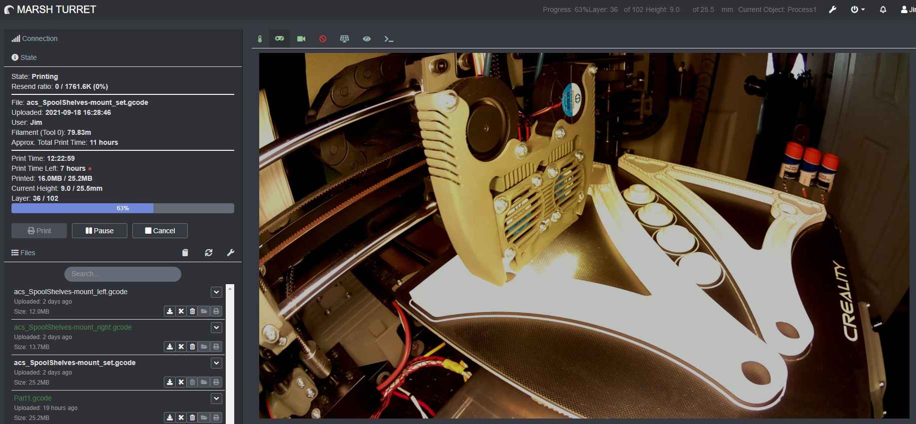
I haven’t yet figured out how to adjust this at the system initialization level, but I found the necessary settings in an OctoPrint plugin. The overall frame became darker, but the object now has the necessary detail.
In a dark room with general lighting off:
With room lighting on:
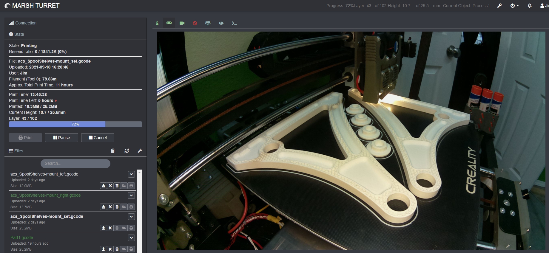
The images are only needed for monitoring the print process: checking for layer shifts, skips, progress, or whether it’s printing at all. There’s no need to take these photos to an art auction or set up a gallery exhibit. It’s purely a matter of technical necessity, and for now, it looks almost the way I want.
That said, there’s still room for improvement in the settings. I’m not a fan of relying on extra plugins. I’m confident that the same results can be achieved directly by editing the config during startup. I just need to read the documentation…
And finally, the problem of the obnoxious blue color of the “arm” holding the camera. This wasn’t a technical issue but an aesthetic one — the blue segments drove me absolutely insane!
After trying several solutions, I found that the least unsightly option was to cover the “arm” with a black nylon cable sleeve:

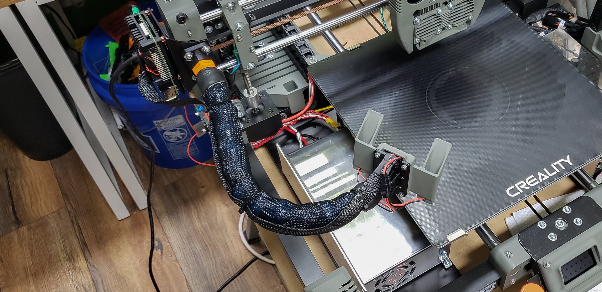
These sleeves are already used extensively in the printer for wiring, so while it does look a bit odd, at least it matches the overall style.
MARSH TURRET as a whole looks strange anyway, so it fits. I’m still undecided about whether I like this solution or not. On the one hand, it feels like a “duct-tape fix” and a bit crude. I should’ve been more persistent in my search for better options. On the other hand, there’s something charming about it — reminiscent of an old space suit’s “hose” leading to its external life-support system. I don’t know… for now, it’s staying as it is.
To round off the OctoPrint topic, here’s a list of all the plugins I use. Some of them might be useful to others. Every plugin in this list has been deemed valuable after years of use, with a couple of recent exceptions.
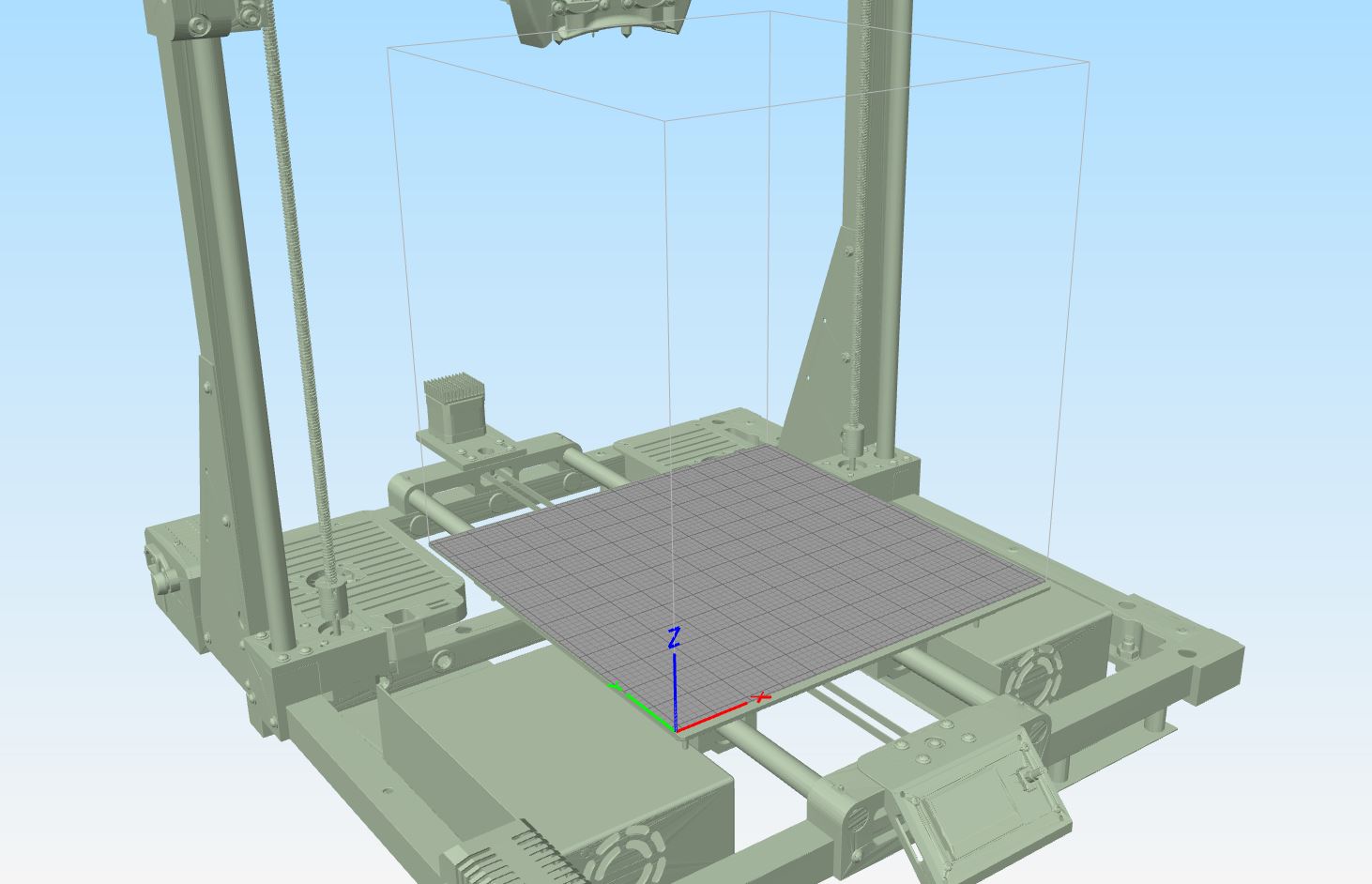
Exception 1: Bed Visualizer
This plugin shows just how uneven your print bed is and helps you level it more effectively. Previously, I didn’t use it because my printers lacked an automatic probe for bed leveling, so leveling was done the old-fashioned way — with a piece of paper.
With the addition of BLTouch and this plugin, the process became much faster and more precise. I also discovered that MARSH TURRET’s bed has a slight hump in the center along the Y-axis:

There’s nothing I can do about it — it’s a defect in the glass itself. No amount of “four-point” leveling will fix it. The chart exaggerates the issue for clarity; the actual deviation is measured in fractions of a millimeter. In any case, the bed’s unevenness is accounted for and compensated during printing. It could’ve been much worse…
Exception 2: Camera Settings
This is another new plugin for me. It allowed me to fix the issue with enabling automatic exposure for the camera, as mentioned earlier. It’s fun to tinker with, offering a ton of camera settings. However, once I figure out how to enforce auto-exposure at startup through the Raspberry Pi’s configuration files, this plugin will become redundant and will be removed.
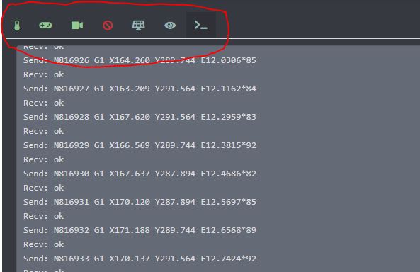
Editing /boot/octopi.txt and the camera_raspi_options config lines didn’t fix the issue. Clearly, there’s another setting somewhere…
Trusted and Longstanding Plugins:
A simple plugin that sends service messages via M117 to the printer’s internal display, showing how many layers have been printed out of the total. On Widow, the original firmware stripped away progress bar functionality from the display, leaving it permanently stuck at 0%. This was infuriating. This plugin provided at least some feedback by displaying the layer count.
This plugin actually updates the progress bar on the printer’s display. However, it requires modifications to the firmware (by default, Marlin disables external control of the progress bar via M73). Eventually, I gave in, updated the firmware, and used this plugin to get a functional progress bar on the display. That said, this plugin doesn’t replace the previous one, as knowing the exact layer count is often just as useful as seeing the overall percentage.
An alternative to OctoPrint’s native temperature graph, this plugin offers more detail, better controls, and the ability to zoom in on specific sections of the graph — a feature I use frequently.
A purely “decorative” plugin that lets you rearrange the interface tabs into a more compact view and order them according to your preferences. You can even remove tab names entirely and replace them with icons from the built-in set:
This plugin lets you change the interface theme. By default, OctoPrint’s interface is overly bright and white — painful to look at in a dimly lit room. Using this plugin, I switched to a darker theme. There’s a whole library of pre-made themes available.
Additionally, it lets you customize or override existing CSS styles. For instance, by default, the interface is designed to fit mobile screens. While that’s great for phones, on a wide computer monitor it results in a narrow column in the center of the screen. By tweaking a few CSS rules, you can stretch the interface to fill the entire window (including temperature graphs and video streams). Here’s what I usually adjust:
Selector = ‘.span8’; CSS-Rule = ‘width’; value = ‘70%’
Selector = ‘.container’; CSS-Rule = ‘width’; value = ‘100%’
Selector = ‘.span4’; CSS-Rule = ‘width’; value = ‘25%’
Selector = ‘.row’; CSS-Rule = ‘margin-left’; value = ‘0’
You can tweak other elements to your liking as well.
While it’s possible to directly edit the CSS file on the HTTP server, I find it tedious, and updates might overwrite your changes. It’s much simpler to use this plugin, click a couple of buttons to choose a dark theme, and adjust four styles.
One of the most popular and visually stunning OctoPrint plugins — and also the most useless from a practical standpoint. But it’s undeniably beautiful. No one can resist its charm. The most common feature is taking a snapshot at the end of every layer, moving the printhead aside so it doesn’t block the view, and then compiling the images into a timelapse video:
Of course, I should’ve moved Turret’s printhead to the other side for the snapshots. By the time I realized this, it was too late. Still, it serves as a demonstration. Normally, I keep this plugin disabled. Beyond its hypnotic effect, it offers little practical value while consuming significant resources. It’s fun but resource-hungry.
These are all the plugins I use with OctoPrint. Of course, the community has created a vast number of additional plugins. But remember, not all plugins are created equal!
That’s how it all came together.
Looking back, I realize I made a significant mistake with Black Widow by tying its functionality entirely to the Raspberry Pi, with its overly flashy, bloated interface and excessive features. Keeping that zoo in working order took far too much time and effort. In hindsight, I fell into the classic trap many 3D printer enthusiasts do — turning a practical household tool into a “printer for the sake of the printer.”
With MARSH TURRET, this mistake was corrected. The Raspberry Pi with OctoPrint and the camera is a useful addition to the device’s functionality, but it doesn’t overcomplicate its overall design. If necessary, I could remove this add-on entirely by unscrewing just four bolts and disconnecting two plugs. MARSH TURRET would lose its remote control and monitoring capabilities but would retain its full local functionality as a 3D printer. It’s a finished product. There’s no need to invent anything else for it. No need to “upgrade” it further. No need for constant maintenance (apart from regular nozzle replacements and cleaning the bed). It’s a sturdy, reliable workhorse — exactly what I needed!
This series of articles has two more planned entries. One will focus on secondary accessories, designed more for fun than for practical use. The other, final article, will provide a thorough post-project breakdown. I’ll attempt to evaluate how well expectations matched reality, showcase staged photos of the finished printer, share examples of prints (including dual-nozzle printing), and so on.
That’s the plan… Stay tuned for the continuation.